Chapter 2 Installing the Router
Installing the Router
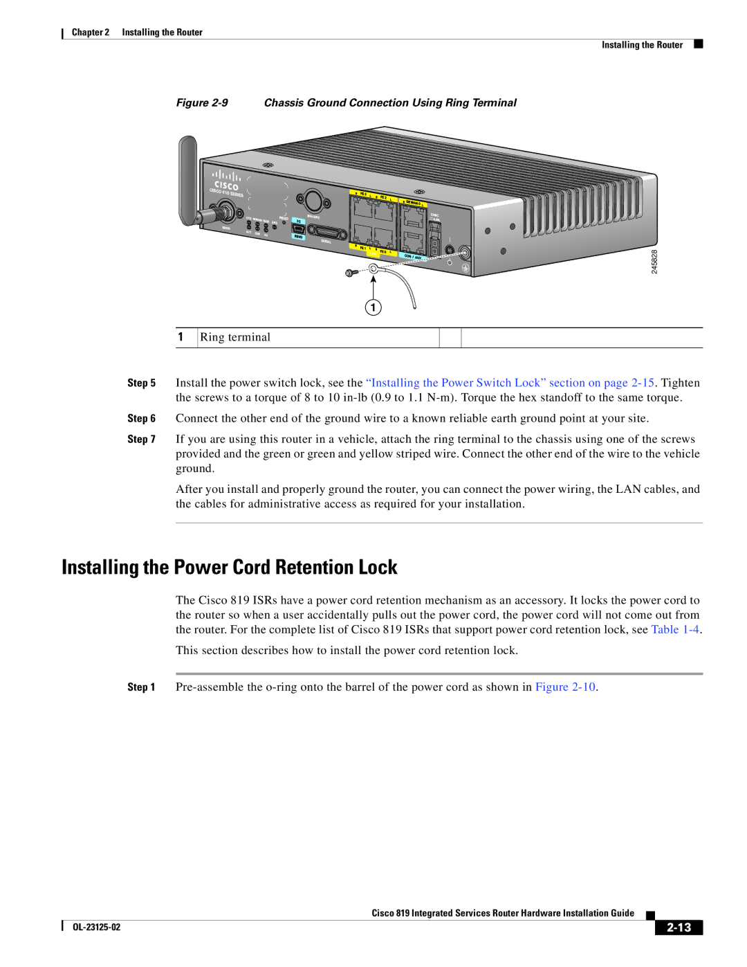
Figure 2-9 Chassis Ground Connection Using Ring Terminal
1
245828
1
Ring terminal
Step 5 Install the power switch lock, see the “Installing the Power Switch Lock” section on page
Step 6 Connect the other end of the ground wire to a known reliable earth ground point at your site.
Step 7 If you are using this router in a vehicle, attach the ring terminal to the chassis using one of the screws provided and the green or green and yellow striped wire. Connect the other end of the wire to the vehicle ground.
After you install and properly ground the router, you can connect the power wiring, the LAN cables, and the cables for administrative access as required for your installation.
Installing the Power Cord Retention Lock
The Cisco 819 ISRs have a power cord retention mechanism as an accessory. It locks the power cord to the router so when a user accidentally pulls out the power cord, the power cord will not come out from the router. For the complete list of Cisco 819 ISRs that support power cord retention lock, see Table
This section describes how to install the power cord retention lock.
Step 1
|
| Cisco 819 Integrated Services Router Hardware Installation Guide |
|
| |
|
|
| |||
|
|
|
| ||
|
|
|
| ||