Replacing the Chassis
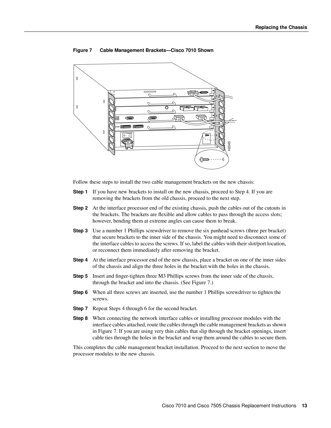
Figure 7 Cable Management Brackets—Cisco 7010 Shown
H2045 |
Follow these steps to install the two cable management brackets on the new chassis:
Step 1 If you have new brackets to install on the new chassis, proceed to Step 4. If you are removing the brackets from the old chassis, proceed to the next step.
Step 2 At the interface processor end of the existing chassis, push the cables out of the cutouts in the brackets. The brackets are flexible and allow cables to pass through the access slots; however, bending them at extreme angles can cause them to break.
Step 3 Use a number 1 Phillips screwdriver to remove the six panhead screws (three per bracket) that secure brackets to the inner side of the chassis. You might need to disconnect some of the interface cables to access the screws. If so, label the cables with their slot/port location, or reconnect them immediately after removing the bracket.
Step 4 At the interface processor end of the new chassis, place a bracket on one of the inner sides of the chassis and align the three holes in the bracket with the holes in the chassis.
Step 5 Insert and
Step 6 When all three screws are inserted, use the number 1 Phillips screwdriver to tighten the screws.
Step 7 Repeat Steps 4 through 6 for the second bracket.
Step 8 When connecting the network interface cables or installing processor modules with the interface cables attached, route the cables through the cable management brackets as shown in Figure 7. If you are using very thin cables that slip through the bracket openings, insert cable ties through the holes in the bracket and wrap them around the cables to secure them.
This completes the cable management bracket installation. Proceed to the next section to move the processor modules to the new chassis.
Cisco 7010 and Cisco 7505 Chassis Replacement Instructions 13