Prerequisites
Note If these conditions are not true, for instance, if you must remove a
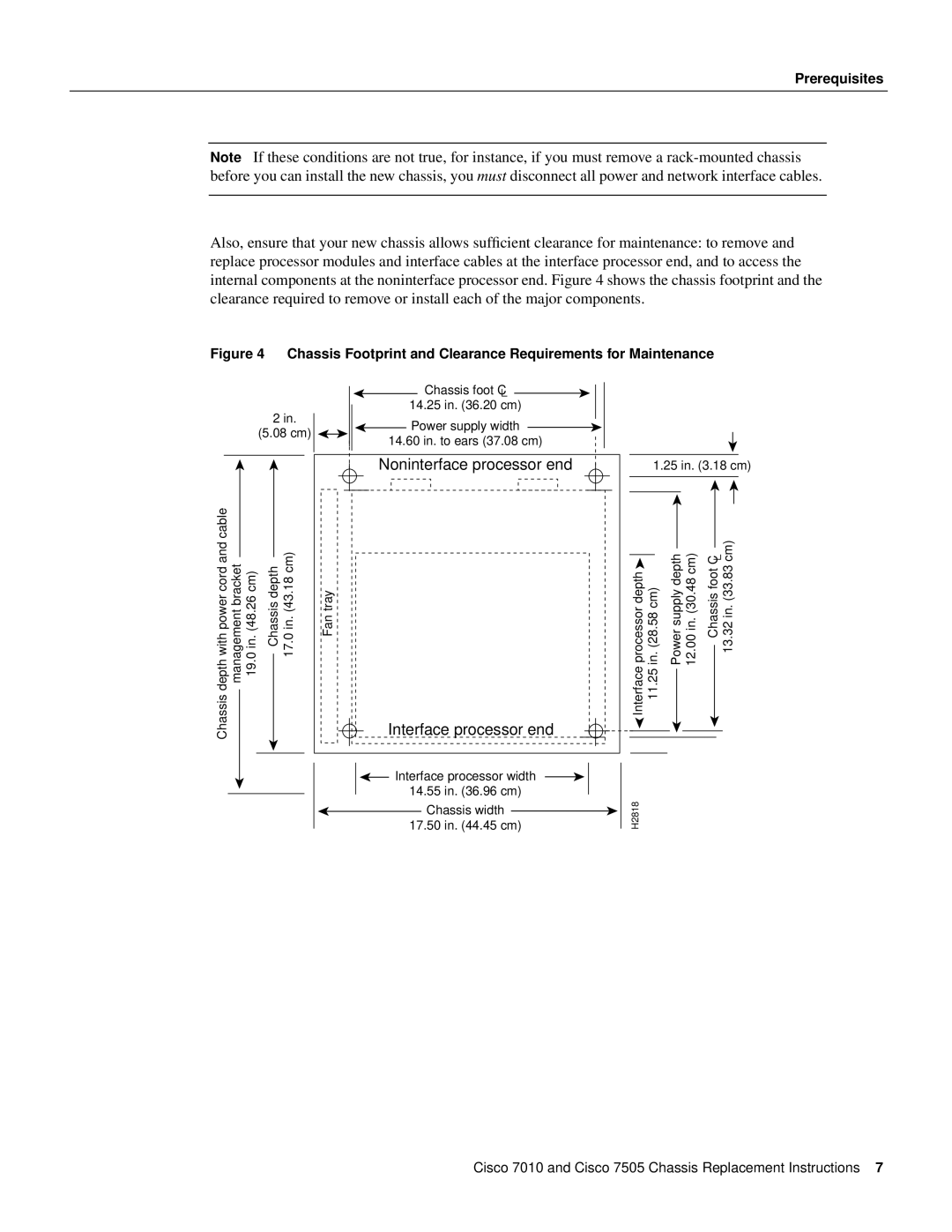
Also, ensure that your new chassis allows sufficient clearance for maintenance: to remove and replace processor modules and interface cables at the interface processor end, and to access the internal components at the noninterface processor end. Figure 4 shows the chassis footprint and the clearance required to remove or install each of the major components.
Figure 4 Chassis Footprint and Clearance Requirements for Maintenance
![]() Chassis foot C
Chassis foot C ![]() 14.25 in. (36.20 cm)
14.25 in. (36.20 cm)
2 in. | Power supply width | |
(5.08 cm) | ||
14.60 in. to ears (37.08 cm) | ||
|
depth with power cord and cable | management bracket 19.0 in. (48.26 cm) | Chassis depth 17.0 in. (43.18 cm) |
Chassis |
|
|
Noninterface processor end
Fan tray
Interface processor end
![]() Interface processor width 14.55 in. (36.96 cm)
Interface processor width 14.55 in. (36.96 cm)
Chassis width
17.50 in. (44.45 cm)
1.25 in. (3.18 cm)
|
|
|
|
|
|
|
|
|
|
|
| 13.32 in. (33.83 cm) |
|
|
|
|
|
|
|
|
|
|
|
|
|
| |
|
|
|
|
|
|
|
|
|
|
| |||
|
|
| Power supply depth 12.00 in. (30.48 cm) | Chassis foot C |
| ||||||||
processor depth | in. (28.58 cm) |
|
|
| |||||||||
|
| ||||||||||||
Interface | 11.25 |
|
|
|
|
|
|
|
|
|
|
| |
|
|
|
|
|
|
|
|
|
|
| |||
|
|
|
|
|
|
|
|
|
|
|
|
|
|
|
|
|
|
|
|
|
|
|
|
|
|
|
|
|
|
|
|
|
|
|
|
|
|
|
|
|
|
H2818
Cisco 7010 and Cisco 7505 Chassis Replacement Instructions 7