Cisco Systems DPC3208, EPC3208 manual Back Panel Description

Models: DPC3208 EPC3208

1 72
Download 72 pages 3.94 Kb
Page 31
Image 31

Back Panel Description

Back Panel Description

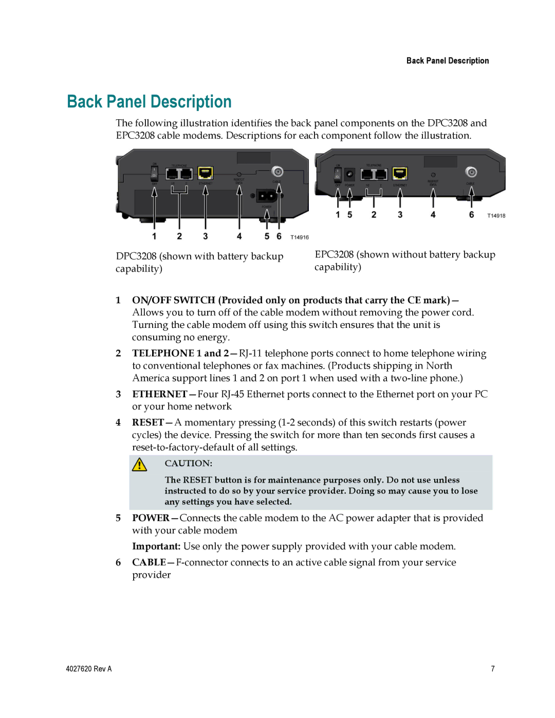
The following illustration identifies the back panel components on the DPC3208 and EPC3208 cable modems. Descriptions for each component follow the illustration.

DPC3208 (shown with battery backup capability)

EPC3208 (shown without battery backup capability)

1ON/OFF SWITCH (Provided only on products that carry the CE mark)— Allows you to turn off of the cable modem without removing the power cord. Turning the cable modem off using this switch ensures that the unit is consuming no energy.

2TELEPHONE 1 and 2—RJ-11 telephone ports connect to home telephone wiring to conventional telephones or fax machines. (Products shipping in North America support lines 1 and 2 on port 1 when used with a two-line phone.)

3ETHERNET—Four RJ-45 Ethernet ports connect to the Ethernet port on your PC or your home network

4RESET—A momentary pressing (1-2 seconds) of this switch restarts (power cycles) the device. Pressing the switch for more than ten seconds first causes a reset-to-factory-default of all settings.

CAUTION:

The RESET button is for maintenance purposes only. Do not use unless instructed to do so by your service provider. Doing so may cause you to lose any settings you have selected.

5POWER—Connects the cable modem to the AC power adapter that is provided with your cable modem

Important: Use only the power supply provided with your cable modem.

6CABLE—F-connector connects to an active cable signal from your service provider

4027620 Rev A

7

Page 31
Image 31
Cisco Systems DPC3208, EPC3208 manual Back Panel Description