Chapter 3 Operation of Front Panel Indicators
Normal Operations (AC Power Applied)
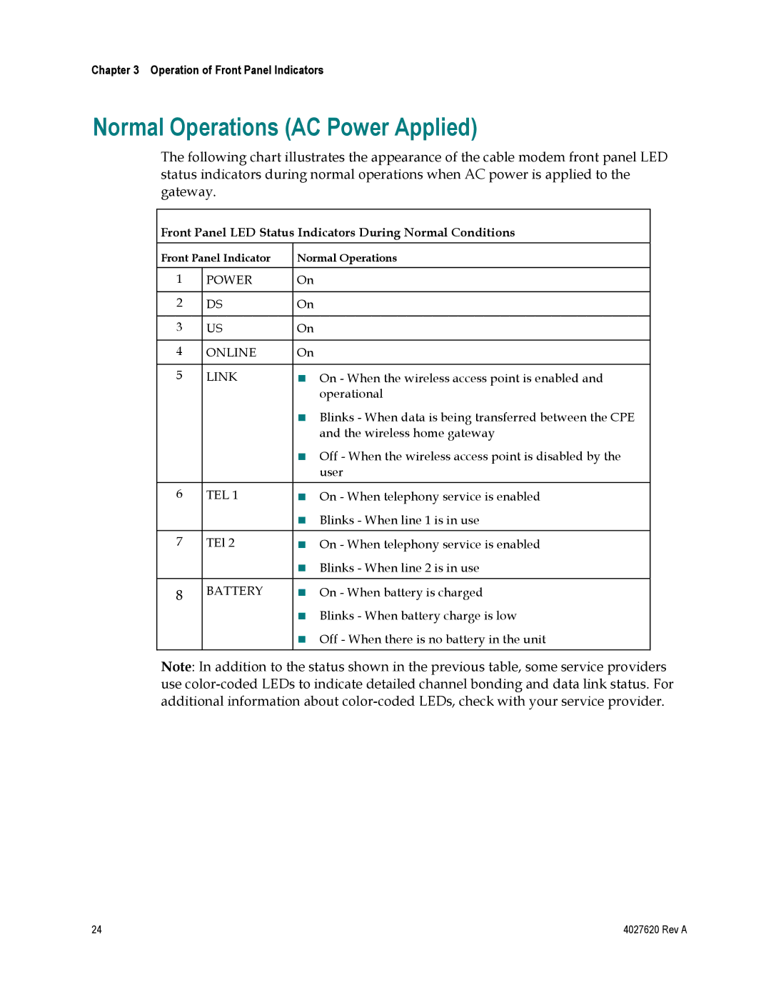
The following chart illustrates the appearance of the cable modem front panel LED status indicators during normal operations when AC power is applied to the gateway.
Front Panel LED Status Indicators During Normal Conditions
Front Panel Indicator | Normal Operations | ||
|
|
|
|
1 | POWER | On |
|
|
|
|
|
2 | DS | On |
|
|
|
|
|
3 | US | On |
|
|
|
|
|
4 | ONLINE | On |
|
|
|
|
|
5 | LINK | | On - When the wireless access point is enabled and |
|
|
| operational |
|
| | Blinks - When data is being transferred between the CPE |
|
|
| and the wireless home gateway |
|
| | Off - When the wireless access point is disabled by the |
|
|
| user |
|
|
|
|
6 | TEL 1 | | On - When telephony service is enabled |
|
| | Blinks - When line 1 is in use |
|
|
|
|
7 | TEl 2 | | On - When telephony service is enabled |
|
| | Blinks - When line 2 is in use |
|
|
|
|
8 | BATTERY | | On - When battery is charged |
|
| | Blinks - When battery charge is low |
|
| | Off - When there is no battery in the unit |
|
|
|
|
Note: In addition to the status shown in the previous table, some service providers use
24 | 4027620 Rev A |
