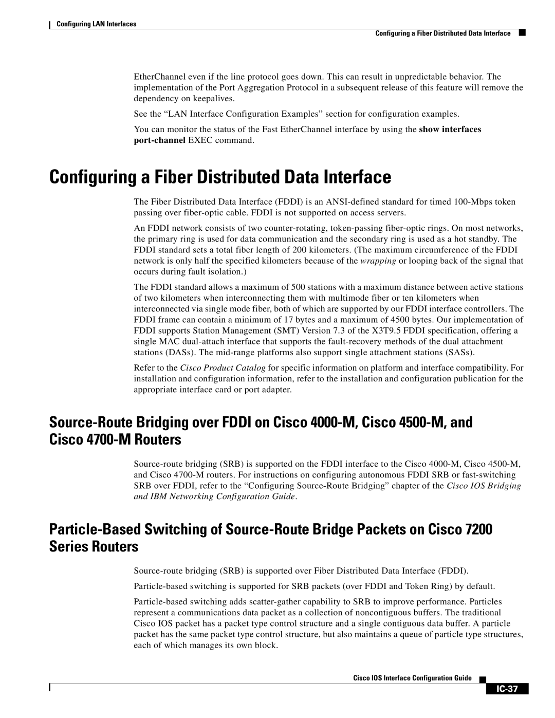
IC-23 specifications
Cisco Systems IC-23 is a robust networking device designed to address the ever-evolving demands of modern enterprises. As part of Cisco's extensive portfolio, the IC-23 serves as an ideal solution for organizations seeking to enhance their network performance, reliability, and scalability.One of the standout features of the Cisco IC-23 is its high-speed connectivity options. With support for both wired and wireless communications, this device can seamlessly integrate into a wide range of network architectures. It offers multiple Gigabit Ethernet ports, enabling rapid data transfer and facilitating the connection of numerous devices without compromising performance.
Another key characteristic of the IC-23 is its advanced security protocols. Data breaches and cyber threats are persistent concerns in today's digital landscape, and Cisco addresses these challenges head-on with robust security measures. The IC-23 incorporates features such as firewall capabilities, intrusion detection systems, and secure VPN support, ensuring that sensitive information remains protected while traversing the network.
The IC-23 also leverages Cisco's renowned software-defined networking (SDN) capabilities. This technology allows businesses to manage their network resources dynamically, ensuring optimal performance based on real-time demands. As a result, organizations can easily adjust their network configurations to meet fluctuating workloads, enhancing both efficiency and cost-effectiveness.
Scalability is another critical feature of the IC-23, making it an excellent choice for growing companies. Cisco has designed this device to accommodate increasing data traffic without necessitating a complete overhaul of existing infrastructure. This adaptability ensures that organizations can expand their networks smoothly as their operations evolve.
Moreover, the IC-23 supports a variety of network management tools, providing IT teams with the insights needed to monitor performance and troubleshoot issues proactively. Cisco's user-friendly interface simplifies the process of network management, allowing administrators to optimize resources and maintain continuous uptime.
In conclusion, Cisco Systems IC-23 stands out as a highly capable networking solution tailored for modern enterprises. With its high-speed connectivity, comprehensive security features, SDN capabilities, scalability, and intuitive management tools, the IC-23 is well-equipped to meet the demands of today’s digital environments. As organizations continue to navigate the complexities of the digital age, the IC-23 prepares them to thrive in an increasingly interconnected world.

