Cisco IE 3010 Switch Getting Started Guide
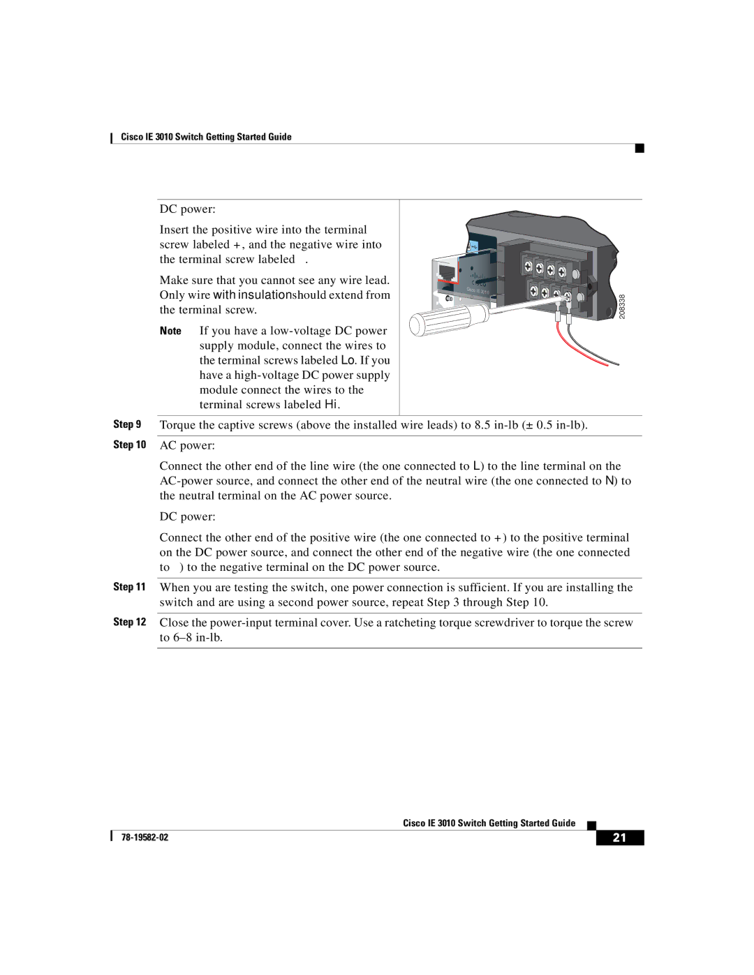
DC power:
Insert the positive wire into the terminal screw labeled +, and the negative wire into the terminal screw labeled
Make sure that you cannot see any wire lead. Only wire with insulation should extend from the terminal screw.
Note If you have a
Cisco IE 30110
 208338
Step 9 Torque the captive screws (above the installed wire leads) to 8.5
Connect the other end of the line wire (the one connected to L) to the line terminal on the
DC power:
Connect the other end of the positive wire (the one connected to +) to the positive terminal on the DC power source, and connect the other end of the negative wire (the one connected to
Step 11 When you are testing the switch, one power connection is sufficient. If you are installing the switch and are using a second power source, repeat Step 3 through Step 10.
Step 12 Close the
|
| Cisco IE 3010 Switch Getting Started Guide |
|
|
|
|
| ||
|
|
| 21 | |
|
|
|