Cisco IE 3010 Switch Getting Started Guide
Step 3 Use a Phillips screwdriver to loosen the captive screw on the
Step 4 Use
Note Use
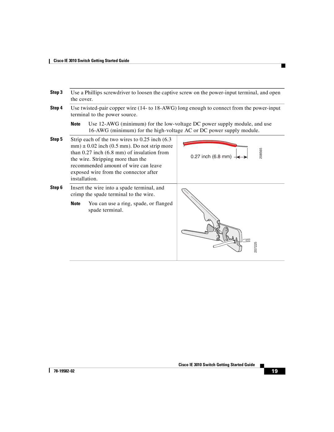
Step 5 Strip each of the two wires to 0.25 inch (6.3
mm)± 0.02 inch (0.5 mm). Do not strip more than 0.27 inch (6.8 mm) of insulation from the wire. Stripping more than the recommended amount of wire can leave exposed wire from the connector after installation.
Step 6 Insert the wire into a spade terminal, and crimp the spade terminal to the wire.
Note You can use a ring, spade, or flanged spade terminal.
0.27 inch (6.8 mm) 


208565
207225
|
| Cisco IE 3010 Switch Getting Started Guide |
|
|
|
|
| ||
|
|
| 19 | |
|
|
|