Chapter 1 Overview

Identifying Interface Addresses

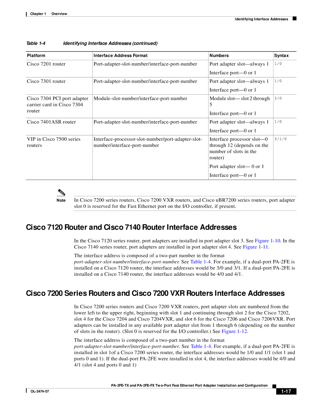
Table 1-4

Identifying Interface Addresses (continued)


Platform


Interface Address Format

Numbers

Syntax


Cisco 7201 router

Port-adapter-slot-number/interface-port-number

Port adapter slot—always 1

1/0


Interface port—0 or 1


Cisco 7301 router

Port-adapter-slot-number/interface-port-number

Port adapter slot—always 1

1/0


Interface port—0 or 1


Cisco 7304 PCI port adapter

Module-slot-number/interface-port-number

Module slot— slot 2 through

3/0

carrier card in Cisco 7304


5


router


Interface port—0 or 1


Cisco 7401ASR router

Port-adapter-slot-number/interface-port-number

Port adapter slot—always 1

1/0


Interface port—0 or 1


VIP in Cisco 7500 series

Interface-processor-slot-number/port-adapter-slot-

Interface processor slot—0

3/1/0

routers


number/interface-port-number

through 12 (depends on the


number of slots in the


router)


Port adapter slot— 0 or 1


Interface port—0 or 1


Note In Cisco 7200 series routers, Cisco 7200 VXR routers, and Cisco uBR7200 series routers, port adapter slot 0 is reserved for the Fast Ethernet port on the I/O controller, if present.

Cisco 7120 Router and Cisco 7140 Router Interface Addresses

In the Cisco 7120 series router, port adapters are installed in port adapter slot 3. See Figure 1-10. In the Cisco 7140 series router, port adapters are installed in port adapter slot 4. See Figure 1-11.

The interface address is composed of a two-part number in the format port-adapter-slot-number/interface-port-number.See Table 1-4. For example, if a dual-port PA-2FE is installed on a Cisco 7120 router, the interface addresses would be 3/0 and 3/1. If a dual-port PA-2FE is installed on a Cisco 7140 router, the interface addresses would be 4/0 and 4/1.

Cisco 7200 Series Routers and Cisco 7200 VXR Routers Interface Addresses

In Cisco 7200 series routers and Cisco 7200 VXR routers, port adapter slots are numbered from the lower left to the upper right, beginning with slot 1 and continuing through slot 2 for the Cisco 7202, slot 4 for the Cisco 7204 and Cisco 7204VXR, and slot 6 for the Cisco 7206 and Cisco 7206VXR. Port adapters can be installed in any available port adapter slot from 1 through 6 (depending on the number of slots in the router). (Slot 0 is reserved for the I/O controller.) See Figure 1-12.

The interface address is composed of a two-part number in the format port-adapter-slot-number/interface-port-number. See Table 1-4. For example, if a dual-port PA-2FE is installed in slot 1of a Cisco 7200 series router, the interface addresses would be 1/0 and 1/1 (slot 1 and ports 0 and 1). If the dual-port PA-2FE were installed in slot 4, the interface addresses would be 4/0 and 4/1 (slot 4 and ports 0 and 1)

PA-2FE-TX and PA-2FE-FX Two-Port Fast Ethernet Port Adapter Installation and Configuration


OL-3474-07

1-17


Page 29
Image 29
Cisco Systems PA-2FE-FX, PA-2FE-TX manual Cisco 7120 Router and Cisco 7140 Router Interface Addresses

PA-2FE-FX, PA-2FE-TX specifications

Cisco Systems PA-2FE-TX and PA-2FE-FX are high-performance Ethernet interface modules designed to enhance the capabilities of Cisco 2600 and 3600 series routers. They provide businesses with flexible and reliable networking solutions that meet the increasing demand for bandwidth and connectivity.

One of the main features of the PA-2FE-TX module is its ability to support two 10/100 Mbps Fast Ethernet interfaces. This allows organizations to connect multiple devices while improving network performance. The PA-2FE-FX module, on the other hand, is designed for optical fiber connections. It features two Fast Ethernet interfaces that utilize an SC connector for easier cable management in fiber optic environments. This capability facilitates long-distance data transmission, making it suitable for backbone connections or inter-building links.

Both modules incorporate advanced technologies to ensure efficient data handling. They support Cisco's Auto-Negotiation feature, enabling devices to automatically select the optimal speed and duplex settings, thus simplifying deployment and reducing configuration errors. This functionality is vital in environments with varied device capabilities, allowing seamless communication across the network.

The PA-2FE-TX and PA-2FE-FX modules utilize Quality of Service (QoS) capabilities to prioritize traffic, ensuring that critical applications receive the necessary bandwidth. This is particularly beneficial for VoIP services, video conferencing, and other latency-sensitive applications. Additionally, the modules offer support for VLANs, allowing organizations to segment their networks effectively and enhance security by isolating sensitive data traffic.

Another important characteristic of these modules is their hot-swappable nature, enabling users to replace them without powering down the router, thus minimizing downtime. This feature is critical for businesses that require high availability and reliability from their networking equipment.

In summary, the Cisco Systems PA-2FE-TX and PA-2FE-FX interface modules stand out for their versatility, enabling businesses to implement customized networking solutions tailored to specific needs. With support for both copper and fiber connections, advanced QoS features, and seamless integration into existing Cisco routers, these modules reinforce Cisco’s commitment to providing innovative, robust network solutions that cater to the demands of modern enterprise environments.