Cisco
Physical Description
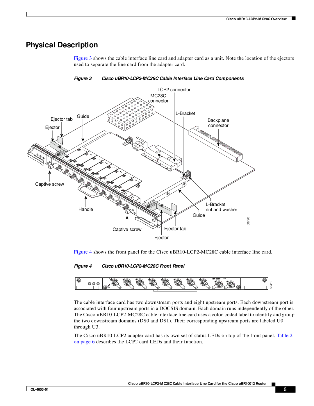
Figure 3 shows the cable interface line card and adapter card as a unit. Note the location of the ejectors used to separate the line card from the adapter card.
Figure 3 Cisco uBR10-LCP2-MC28C Cable Interface Line Card Components
| LCP2 connector |
| MC28C |
| connector |
Ejector tab Guide | |
Backplane | |
Ejector | connector |
|
ENABLED |
|
US0 |
|
| US1 |
| US2 |
| US3 |
Captive screw | US4 |
US5 |
US6
US7
uBR- MC28C DS0
DS1
Handle
Captive screw
nut and washer
Guide
58720
Ejector tab
Ejector
Figure 4 shows the front panel for the Cisco uBR10-LCP2-MC28C cable interface line card.
Figure 4 Cisco uBR10-LCP2-MC28C Front Panel
US0 | US1 | US2 | US3 | US0 | US1 | US2 | US3 |
ENABLED |
|
|
|
|
|
|
|
uBR - MC28C
DS0 | DS1 |
56419
The cable interface card has two downstream ports and eight upstream ports. Each downstream port is associated with four upstream ports in a DOCSIS domain. Each domain runs independently of the other. The Cisco
The Cisco
Cisco
| 5 |
| |
|
|