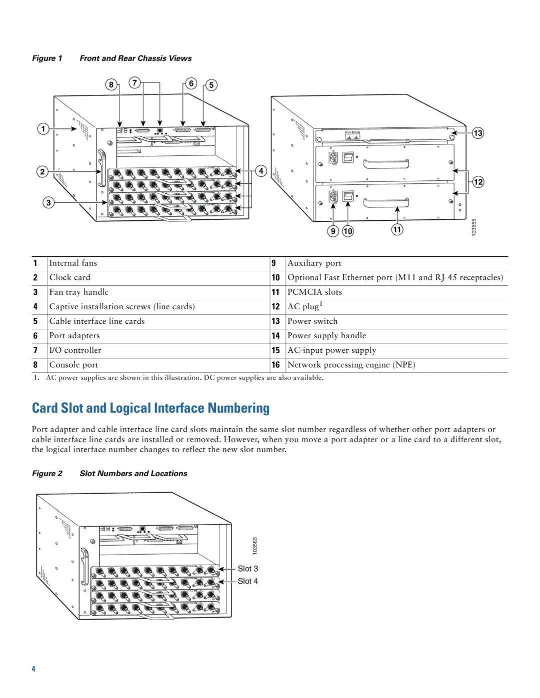
Figure 1 Front and Rear Chassis Views
8 | 7 | 6 |
1
2
3
5
uBR - MC28U | DS0- | DS1- |
| RF | RF |
uBR - MC28U | DS0- | DS1- |
| RF | RF |
uBR - MC28U | DS0- | DS1- |
| RF | RF |
uBR - MC28U | DS0- | DS1- |
| RF | RF |
4
9 | 10 | 11 |
13
12
103555
1 | Internal fans | 9 | Auxiliary port |
|
|
|
|
2 | Clock card | 10 | Optional Fast Ethernet port (M11 and |
|
|
|
|
3 | Fan tray handle | 11 | PCMCIA slots |
|
|
|
|
4 | Captive installation screws (line cards) | 12 | AC plug1 |
5 | Cable interface line cards | 13 | Power switch |
|
|
|
|
6 | Port adapters | 14 | Power supply handle |
|
|
|
|
7 | I/O controller | 15 | |
|
|
|
|
8 | Console port | 16 | Network processing engine (NPE) |
|
|
|
|
1. AC power supplies are shown in this illustration. DC power supplies are also available.
Card Slot and Logical Interface Numbering
Port adapter and cable interface line card slots maintain the same slot number regardless of whether other port adapters or cable interface line cards are installed or removed. However, when you move a port adapter or a line card to a different slot, the logical interface number changes to reflect the new slot number.
Figure 2 Slot Numbers and Locations
uBR - MC28U
uBR - MC28U
uBR - MC28U
DS0- | DS1- |
RF | RF |
DS0- | DS1- |
RF | RF |
DS0- | DS1- |
RF | RF |
103563
![]() Slot 3
Slot 3 ![]() Slot 4
Slot 4
uBR - MC28U
DS0- | DS1- |
RF | RF |
4
