Working Inside the Blade Server
C o m m e n t s t o u c s - d o c f e e d b a ck @ c i s c o . c o m
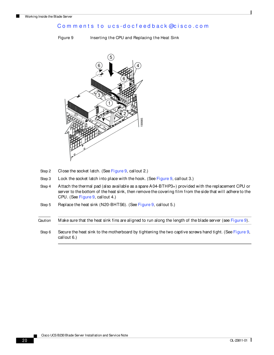
Figure 9 Inserting the CPU and Replacing the Heat Sink
| 5 |
6 | 4 |
| 6 |
3 |
|
| 1 |
| 2 |
| 199985 |
Step 2 Close the socket latch. (See Figure 9, callout 2.)
Step 3 Lock the socket latch into place with the hook. (See Figure 9, callout 3.)
Step 4 Attach the thermal pad (also available as a spare
Step 5 Replace the heat sink
Caution Make sure that the heat sink fins are aligned to run along the length of the blade server (see Figure 9).
Step 6 Secure the heat sink to the motherboard by tightening the two captive screws hand tight. (See Figure 9, callout 6.)
Cisco UCS B230 Blade Server Installation and Service Note
20 |
| |
|