ESC * m n1 n2 [d] k
[Function] | Specifying the Bit Image Mode |
|
|
|
|
| ||
[Code] | <1B>H<2A>H<m><n1><n2> [d] k |
|
|
|
|
| ||
[Range] | {m= 0, 1, 20, 21(Hex)} |
|
|
|
|
| ||
| {0 =< n1 =< FF(Hex)} |
|
|
|
|
| ||
| {0 =< n2 =< 1(Hex)} |
|
|
|
|
| ||
| {0 =< d =< FF(Hex)} |
|
|
|
|
| ||
| {k = n1 + FF(Hex) x n2} (m=0, 1(Hex)) Number of bytes containing image data | |||||||
| {k = (n1 + FF(Hex) x n2) x 3} (m=20, 21(Hex)) Number of bytes containing image data | |||||||
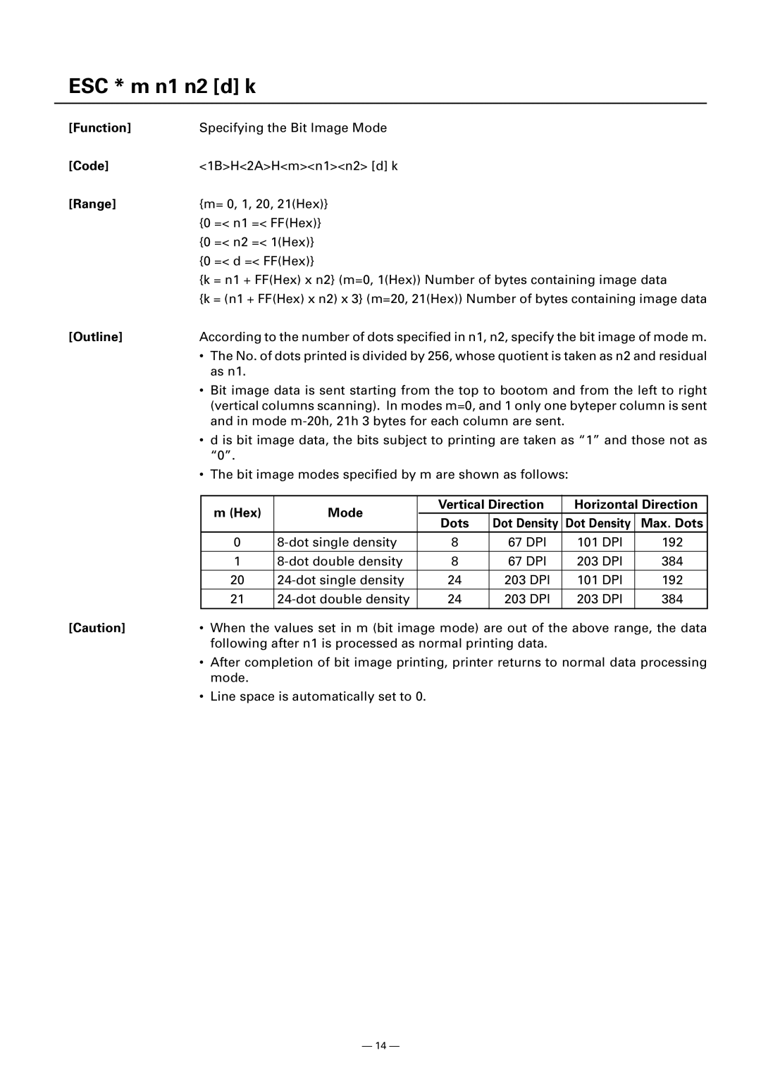
[Outline] | According to the number of dots specified in n1, n2, specify the bit image of mode m. | |||||||
| • | The No. of dots printed is divided by 256, whose quotient is taken as n2 and residual | ||||||
|
| as n1. |
|
|
|
|
|
|
| • | Bit image data is sent starting from the top to bootom and from the left to right | ||||||
|
| (vertical columns scanning). In modes m=0, and 1 only one byteper column is sent | ||||||
|
| and in mode |
|
| ||||
| • d is bit image data, the bits subject to printing are taken as “1” and those not as | |||||||
|
| “0”. |
|
|
|
|
|
|
| • | The bit image modes specified by m are shown as follows: |
|
| ||||
|
|
|
|
|
|
|
| |
|
| m (Hex) | Mode | Vertical Direction |
| Horizontal Direction | ||
|
| Dots | Dot Density | Dot Density | Max. Dots | |||
|
|
|
| |||||
|
| 0 | 8 | 67 DPI |
| 101 DPI | 192 | |
|
|
|
|
|
|
|
|
|
|
| 1 | 8 | 67 DPI |
| 203 DPI | 384 | |
|
| 20 | 24 | 203 DPI |
| 101 DPI | 192 | |
|
| 21 | 24 | 203 DPI |
| 203 DPI | 384 | |
[Caution] | • | When the values set in m (bit image mode) are out of the above range, the data | ||||||
|
| following after n1 is processed as normal printing data. |
|
| ||||
•After completion of bit image printing, printer returns to normal data processing mode.
•Line space is automatically set to 0.
— 14 —
