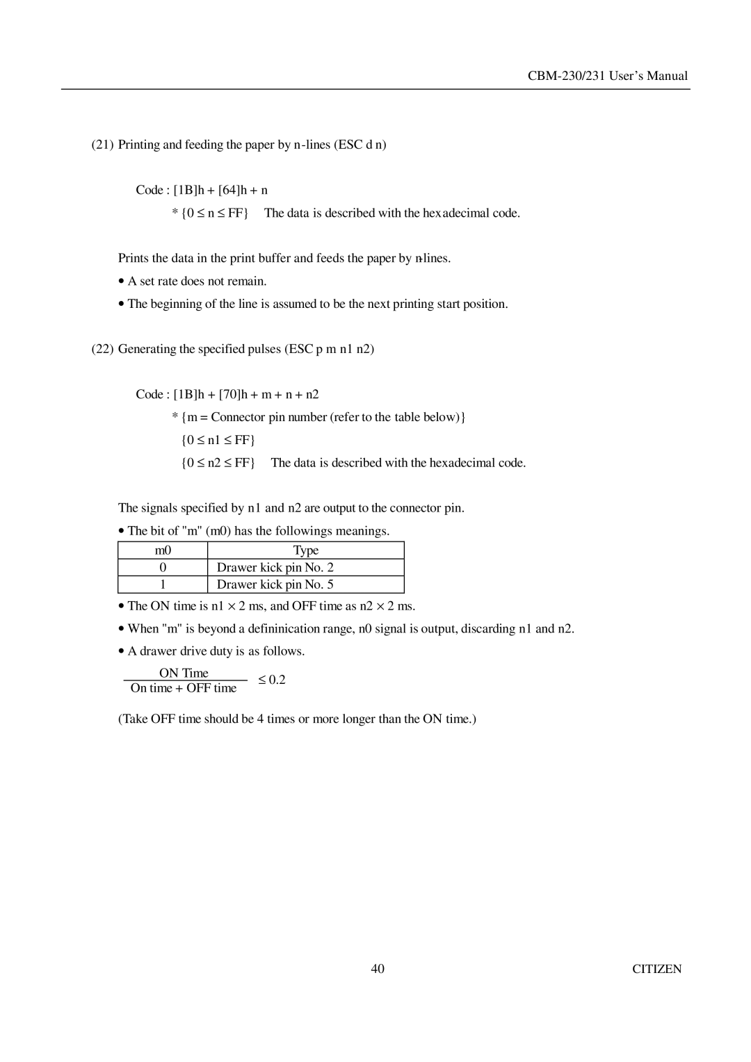
(21) Printing and feeding the paper by
Code : [1B]h + [64]h + n
* {0 ≤ n ≤ FF} The data is described with the hexadecimal code.
Prints the data in the print buffer and feeds the paper by
•A set rate does not remain.
•The beginning of the line is assumed to be the next printing start position.
(22)Generating the specified pulses (ESC p m n1 n2)
Code : [1B]h + [70]h + m + n + n2
* {m = Connector pin number (refer to the table below)}
{0 ≤ n1 ≤ FF} |
|
{0 ≤ n2 ≤ FF} | The data is described with the hexadecimal code. |
The signals specified by n1 and n2 are output to the connector pin.
•The bit of "m" (m0) has the followings meanings.
m0 | Type |
0Drawer kick pin No. 2
1Drawer kick pin No. 5
•The ON time is n1 ⋅ 2 ms, and OFF time as n2 ⋅ 2 ms.
•When "m" is beyond a defininication range, n0 signal is output, discarding n1 and n2.
•A drawer drive duty is as follows.
ON Time
On time + OFF time
(Take OFF time should be 4 times or more longer than the ON time.)
40 | CITIZEN |
