(8) Specifying the Bit Image Mode (ESC * m n1 n2 D1 - Dn) Code : [1B]h + [2A]h + m + n1 + n2 + Dn
*{m= bit image mode (See the table below.)} {0 ≤ n1 ≤ FF}
{0 ≤ n2 ≤ 02} Data is described in Hex code.
According to the bit image mode assigned in m, prints data in the bit image.
•The no. of dots printed is divided by 256, whose quotient is taken as n2 and residualas n1.
•The total no. of dots printed in the bit image is equal to n1 + (256 x n2).
•When bit image data have been input in excess of 1 dot/line (448 dots) position, the excess data are discarded.
•In the bit image data (Dn), the bits subject to printing are taken as "1" and those not as "0".
•The bit image modes are shown as follows:
|
| VERTICAL DIRECTION | HORIZONTAL DIRECTION | |||
m(Hex) | MODE | NO. OF DOTS | DOT DENSITY | DOT DENSITY | MAX. NO OF DOTS | |
0 | 8 | 78 | DPI | 77 DPI | 224 | |
1 | 8 | 78 | DPI | 154 DPI | 448 | |
32 | 16 | 156 | DPI | 77 DPI | 224 | |
33 | 16 | 156 | DPI | 154 DPI | 448 | |
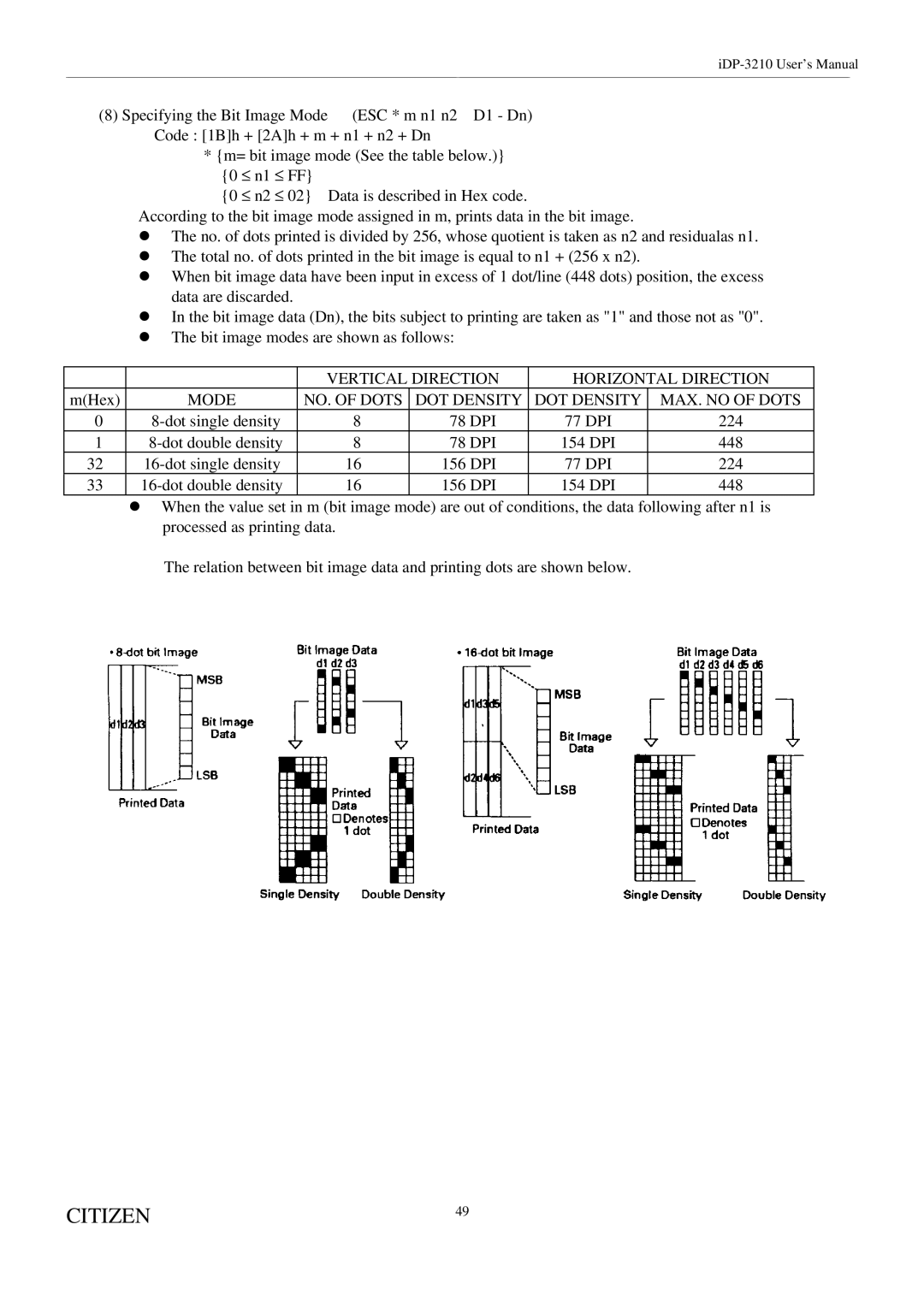
•When the value set in m (bit image mode) are out of conditions, the data following after n1 is processed as printing data.
The relation between bit image data and printing dots are shown below.
CITIZEN | 49 |
|