CHAPTER 2: Installation
Hardware Setup
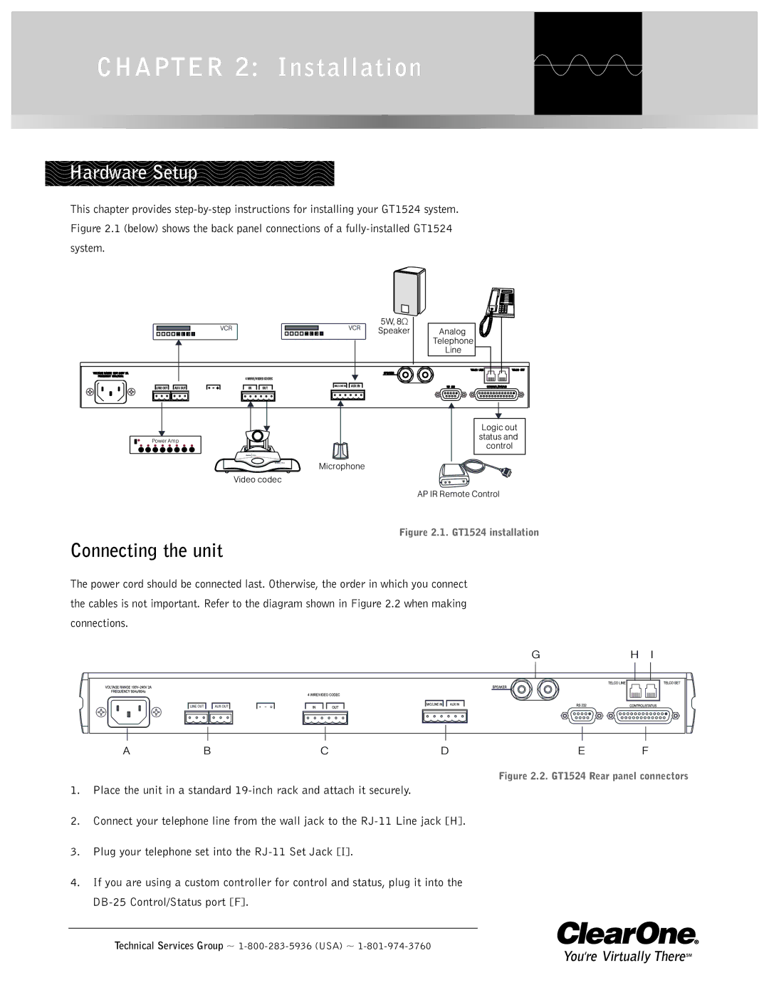
This chapter provides
5W, 8Ω
Speaker
Analog
Telephone
Line
4 WIRE/VIDEO CODEC
LINE OUT | AUX OUT | IN | OUT | MIC/LINE IN | AUX IN |
| Logic out | |
Power Amp | status and | |
control | ||
|
Microphone
Video codec
AP IR Remote Control
Figure 2.1. GT1524 installation
Connecting the unit
The power cord should be connected last. Otherwise, the order in which you connect the cables is not important. Refer to the diagram shown in Figure 2.2 when making connections.
GH I
ABCDE F
Figure 2.2. GT1524 Rear panel connectors
1.Place the unit in a standard
2.Connect your telephone line from the wall jack to the
3.Plug your telephone set into the
4.If you are using a custom controller for control and status, plug it into the