4 | Introduction ~ Controls and Connections |
C.LED Meter. The LED bar meter displays the audio level of any input or output of the GT1524 as well as the Echo Return Loss (ERL) and Echo Return Loss Enhancement (ERLE) between the Speaker/Line Out and the Mic/Line audio input channel. The LED meter also displays Telco Echo Return Loss (TERL) and Telco Echo Return Loss Enhancement (TERLE) for the telephone hybrid.
D.Meter. This button displays the Meter branch of the GT1524’s LCD menu tree from which you can view or enter settings.
E.On. The On button connects and adapts the GT1524 to the telephone line. Pressing and holding the On button for more than two seconds while the GT1524 is active sends a noise burst to readapt the unit to the phone line. A short tone (1000Hz) is sent out the Speaker and Line outputs to indicate that the GT1524 is connected to the line.
F.Off. The Off switch disconnects the GT1524 from the telephone line and mutes all transmit audio to and from the telephone line. A short tone (400Hz) is sent out the Speaker and Line Outputs to notify the user that the GT1524 is disconnected from the line.
Rear panel
GH I
AB
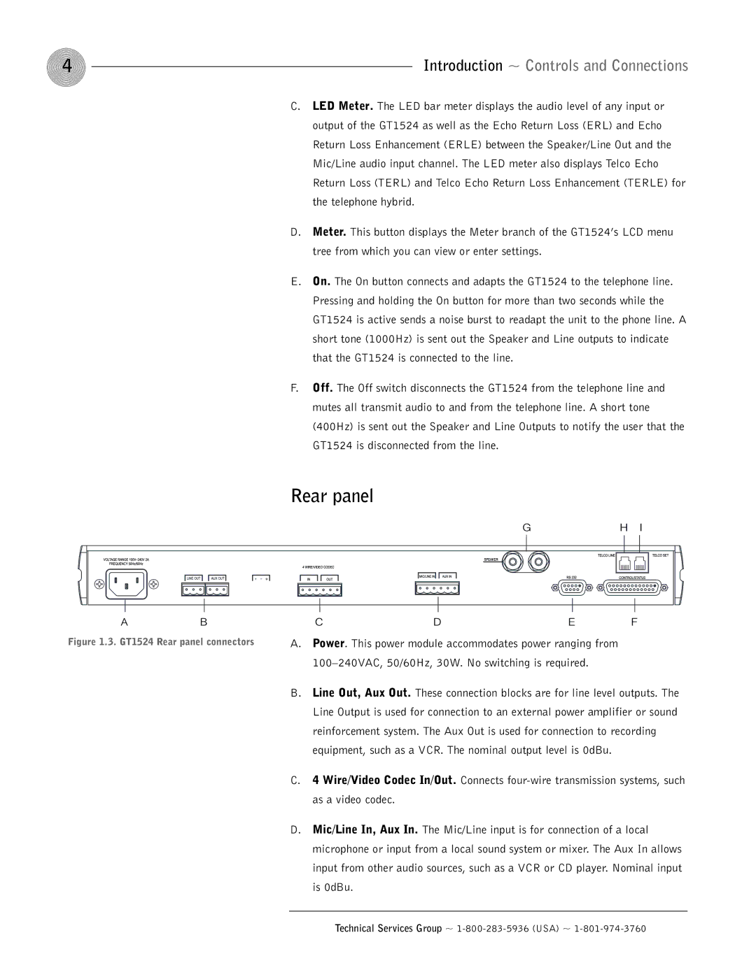
Figure 1.3. GT1524 Rear panel connectors
CDE F
A.Power. This power module accommodates power ranging from
B.Line Out, Aux Out. These connection blocks are for line level outputs. The Line Output is used for connection to an external power amplifier or sound reinforcement system. The Aux Out is used for connection to recording equipment, such as a VCR. The nominal output level is 0dBu.
C.4 Wire/Video Codec In/Out. Connects
D.Mic/Line In, Aux In. The Mic/Line input is for connection of a local microphone or input from a local sound system or mixer. The Aux In allows input from other audio sources, such as a VCR or CD player. Nominal input is 0dBu.
Technical Services Group ~
