Rear I/O Module Installation
If you are installing an openGearTM card in a
If you received a custom rear I/O module for your openGearTM card, you will need to install the I/O module in your 8310 frame before you can connect cables.
Use the following procedure to install the
1.Ensure that the frame is properly installed according to instructions in the section “Installing the Frame” of this manual.
2.On the rear of the 8310, locate the card frame slot.
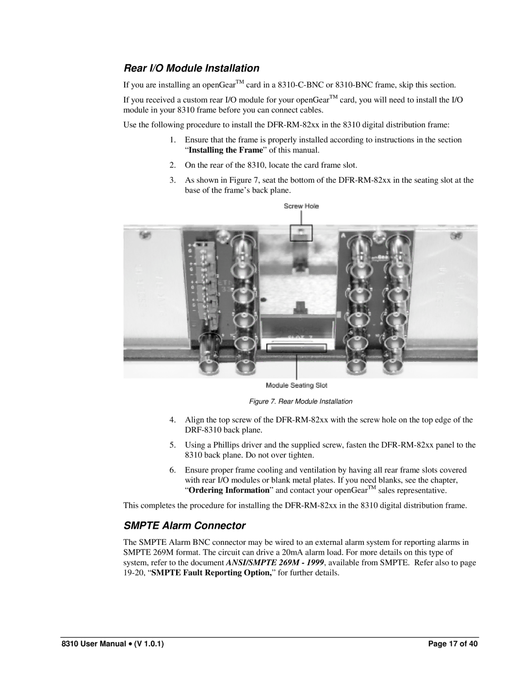
3.As shown in Figure 7, seat the bottom of the
Figure 7. Rear Module Installation
4.Align the top screw of the
5.Using a Phillips driver and the supplied screw, fasten the
6.Ensure proper frame cooling and ventilation by having all rear frame slots covered with rear I/O modules or blank metal plates. If you need blanks, see the chapter, “Ordering Information” and contact your openGearTM sales representative.
This completes the procedure for installing the
SMPTE Alarm Connector
The SMPTE Alarm BNC connector may be wired to an external alarm system for reporting alarms in SMPTE 269M format. The circuit can drive a 20mA alarm load. For more details on this type of system, refer to the document ANSI/SMPTE 269M - 1999, available from SMPTE. Refer also to page
8310 User Manual • (V 1.0.1) | Page 17 of 40 |