1.Open the
•Fan PCB
•Fan Filter
•8 nuts
•8 washers
•
2.Turn frame power off.
3.Open the frame door.
4.Carefully remove the door from the frame by unscrewing the two screws that attach the door to the extender arms.
5.Place the frame door inside up on a clean antistatic workspace.
6.Insert the Fan Filter with the panhandle over the smaller fan vents and the cut corner adjacent to the LED pipes already on the door. Gently push the filter down so the mounting bolts pass through cleanly.
7.Place a washer on each of the 8 mounting bolts.
8.Align the Fan PCB with the fans up so the LED pipes pass through their board holes.
9.Ensure the Alarm Mute button clears its door hole and that the Fault and Fan Fail LEDs clear their door holes while you slowly press the Fan PCB down onto the 8 mounting bolts. See Figure 11 for details on these item locations.
10.On the frame door, check that the Alarm Mute button pushes in and out without binding.
11.Tighten the 8 nuts until they just make contact with the rubber grommets on the
12.Reconnect the door to the frame extender arms with the two screws from step 4.
This completes the procedure to install the Fan Board component of the
Cooling Fan Functions and User Controls
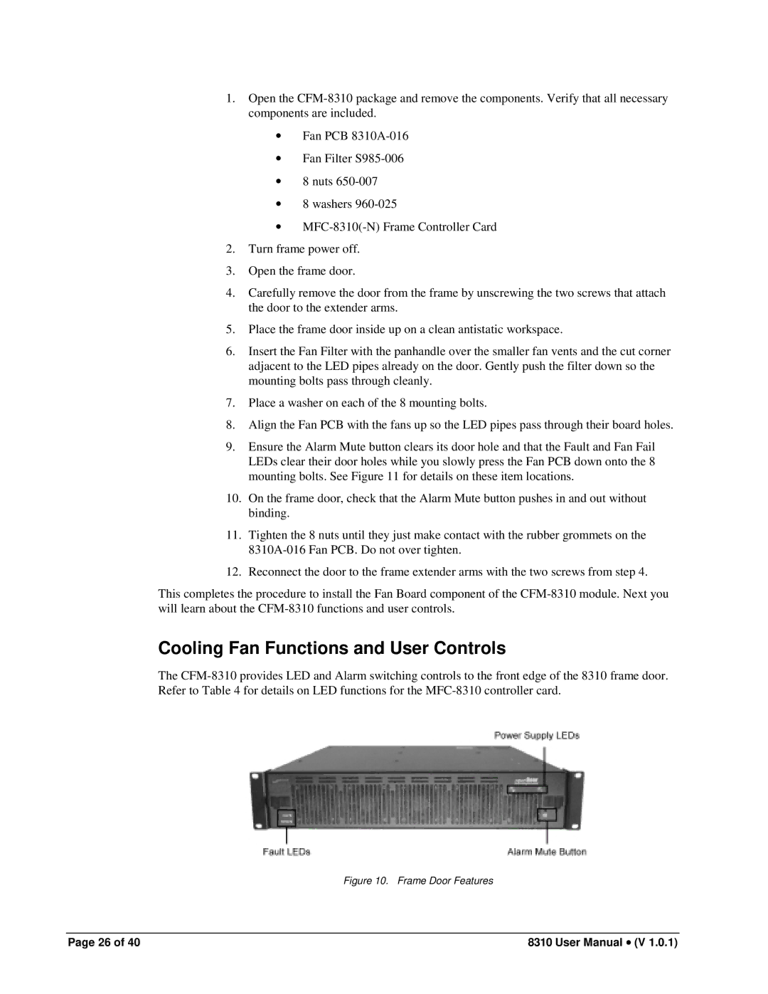
The
Figure 10. Frame Door Features
Page 26 of 40 | 8310 User Manual • (V 1.0.1) |
