292043-UIM-B-0707

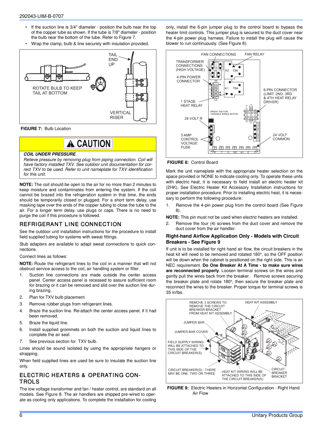
If the suction line is 3/4" diameter - position the bulb near the top of the copper tube as shown. If the tube is 7/8" diameter - position the bulb near the bottom of the tube. Refer to Figure 7.

Wrap the clamp, bulb & line securely with insulation provided.

TAIL

END

UP

*

ROTATE BULB TO KEEP

TAIL AT BOTTOM

VERTICAL

RISER

FIGURE 7: Bulb Location

COIL UNDER PRESSURE.

Relieve pressure by removing plug from piping connection. Coil will have factory installed TXV. See outdoor unit documentation for cor- rect TXV to be used. Refer to unit nameplate for TXV identification for this unit.

NOTE: The coil should be open to the air for no more than 2 minutes to keep moisture and contaminates from entering the system. If the coil cannot be brazed into the refrigeration system in that time, the ends should be temporarily closed or plugged. For a short term delay, use masking tape over the ends of the copper tubing to close the tube to the air. For a longer term delay, use plugs or caps. There is no need to purge the coil if this procedure is followed.

REFRIGERANT LINE CONNECTION

See the outdoor unit installation instructions for the procedure to install field supplied tubing for systems with sweat fittings.

Stub adapters are available to adapt sweat connections to quick con- nections.

Connect lines as follows:

NOTE: Route the refrigerant lines to the coil in a manner that will not obstruct service access to the coil, air handling system or filter.

1.

Suction line connections are made outside the center access


panel. Center access panel is recessed to assure sufficient room


for brazing or it can be removed and slid over the suction line dur-


ing brazing.

2.

Plan for TXV bulb placement.

3.

Remove rubber plugs from refrigerant lines.

4.

Braze the suction line. Re-attach the center access panel, if it had


been removed.

only, install the 6-pin jumper plug to the control board to bypass the heater limit controls. This jumper plug is secured to the duct cover near the 4-pin power plug harness. Failure to install the plug will cause the blower to run continuously. (See Figure 8).

FAN CONNECTIONS

FAN RELAY

TRANSFORMER


F


CONNECTIONS

L

A

L


2

N

1


(HIGH VOLTAGE)


K2 T9A


L


L


4-PIN POWER

2


1


CONNECTOR

L2

1

H 2

K1

T9A

6-PIN CONNECTOR

L 3


(LIMIT, 2ND, 3RD

L 4


& 4TH HEAT RELAY

1 STAGE


DRIVER)

HEAT RELAY


&

LIM


HEAT


FAN

&


LIM

COM


PWR

TEST

BREAK TAB FOR


VARIABLE SPEED MOTOR


24 VOLT R

HEAT 2

HEAT 4


DRV HEAT 3

DRV


DRV

ECM


2


4

LTRIP


C


V


A


5 AMP

5

SPEED2

24 VOLT

M

CONTROL

A

COMMON

P

VOLTAGE

M


X


A


FUSE


R Y G W2 W1 O

C


FIGURE 8: Control Board

Mark the unit nameplate with the appropriate heater selection on the space provided or NONE to indicate cooling only. To operate these units with electric heat, it is necessary to field install an electric heater kit (2HK). See Electric Heater Kit Accessory Installation instructions for proper installation procedure. Prior to installing electric heat, it is neces- sary to perform the following procedure:

1.Remove the 4-pin power plug from the control board (See Figure 8).

NOTE: This pin must not be used when electric heaters are installed.

2.Remove the four (4) screws from the duct cover and remove the duct cover from the air handler.

Right-hand Airflow Application Only - Models with Circuit Breakers - See Figure 9

If unit is to be installed for right hand air flow, the circuit breakers in the heat kit will need to be removed and rotated 180°, so the OFF position will be down when the cabinet is positioned on the right side. This is an NEC requirement. Do One Breaker At A Time - to make sure wires are reconnected properly. Loosen terminal screws on the wires and gently pull the wires back from the breaker. Remove screws securing the breaker plate and rotate 180°, then secure the breaker plate and reconnect the wires to the breaker. Proper torque for terminal screws is 35 in/lbs.

REMOVE 3 SCREWS TO

HEAT KIT ASSEMBLY

REMOVE THE CIRCUIT


BREAKER BRACKET


FROM HEAT KIT ASSEMBLY


5.

Braze the liquid line.

6.

Install supplied grommets on both the suction and liquid lines to


complete the air seal.

7.

See previous section for TXV bulb.

Lines should be sound isolated by using the appropriate hangers or strapping.

When field supplied lines are used be sure to insulate the suction line only.

ELECTRIC HEATERS & OPERATING CON- TROLS

JUMPER BAR

JUMPER BAR COVER

FIELD SUPPLY WIRING WILL BE ATTACHED TO THIS SIDE OF THE CIRCUIT BREAKER(S)

CIRCUIT BREAKER(S) - THERE MAY BE ONE, TWO OR THREE

HEAT KIT WIRING WILL BE ATTACHED TO THIS SIDE OF THE CIRCUIT BREAKER(S)

CIRCUIT BREAKER BRACKET

The low voltage transformer and fan / heater control, are standard on all models. See Figure 8. The air handlers are shipped pre-wired to oper- ate as cooling only applications. To complete the installation for cooling

FIGURE 9: Electric Heaters in Horizontal Configuration - Right Hand Air Flow

6

Unitary Products Group

Page 6
Image 6
Coleman F*FP installation manual Refrigerant Line Connection

F*FP specifications

The Coleman F*FP, an innovative product from the renowned outdoor gear manufacturer Coleman, represents a significant leap forward in portable lighting solutions. Designed for outdoor enthusiasts, campers, and emergency preparedness, this compact device merges functionality with cutting-edge technology.

One of the standout features of the Coleman F*FP is its impressive brightness, which can easily illuminate small campsites or provide adequate light for activities such as cooking or reading after sunset. With adjustable brightness settings, users can customize the light output according to their specific needs, effectively conserving battery life when full brightness isn’t necessary.

The Coleman F*FP incorporates advanced LED technology, ensuring longevity and efficiency. Unlike traditional incandescent bulbs, the LEDs offer a much longer lifespan and consume significantly less power, making them an ideal choice for outdoor use where access to electricity may be limited. This energy-efficient design makes the F*FP not only cost-effective but also environmentally friendly.

Portability is another key characteristic of the Coleman F*FP. The device is lightweight and compact, making it easy to pack and transport, whether you're heading on a weekend camping trip or preparing for an emergency situation. It typically features a built-in handle or a hook for easy hanging, allowing for versatile placement in tents, trees, or outdoor structures.

Durability is paramount when it comes to outdoor equipment, and the Coleman F*FP does not disappoint. Constructed with weather-resistant materials, it can withstand various environmental conditions, from rain to dust, ensuring reliable performance and longevity. This rugged construction makes it a trustworthy companion for any outdoor adventure.

The F*FP also includes user-friendly features such as easy-to-navigate controls and battery indicators. Some models may offer rechargeable options, reducing the need for disposable batteries and enhancing sustainability.

In summary, the Coleman F*FP stands out in the realm of outdoor lighting solutions. Its impressive brightness, energy-efficient LED technology, portability, and durable construction make it an essential tool for adventurers and a sensible choice for emergency preparedness. With the Coleman F*FP in tow, users can enjoy peace of mind and a well-lit experience in the great outdoors.