292043-UIM-B-0707

DUCT CONNECTIONS

Use 1/2" screws to connect ductwork to bottom of unit. Longer screws will pierce the drain pan and cause leakage. If pilot holes are drilled, drill only though field duct and unit bottom flange.

NOTE: The electric heat accessory should be installed before the sup- ply air duct is attached to the supply air openings. Refer to the electric heater kit instructions for proper installation.

Air supply and return may be handled in one of several ways best suited to the installation. See Figure 4 for dimensions for duct inlet and outlet connections.

The vast majority of problems encountered with combination heating and cooling systems can be linked to improperly designed or installed duct systems. It is therefore highly important to the success of an instal- lation that the duct system be properly designed and installed.

Use flexible duct collars to minimize the transmission of vibration/noise into the conditioned space. If electric heat is used, non-flammable material must be used.

Where return air duct is short, or where sound may be a problem, sound absorbing glass fiber should be used inside the duct. Insulation of duct work is a must where it runs through an unheated space during the heating season or through an uncooled space during the cooling season. The use of a vapor barrier is recommended to prevent absorp- tion of moisture from the surrounding air into the insulation.

The supply air duct should be properly sized by use of a transition to match unit opening. All ducts should be suspended using flexible hang- ers and never fastened directly to the structure. This unit is not designed for non-ducted (freeblow) applications. Size outlet plenum or transition to discharge opening sizes shown in Figure 4.

Duct work should be fabricated and installed in accordance with local and/or national codes. This includes the standards of the National Fire Protection Association for Installation of Air-Conditioning and Ventilat- ing Systems, NFPA No. 90B.

AIR FILTERS

Air filters must be field supplied. A 1" filter access rack has been built into the unit. See Figure 4. Remove filter access cover shown. Install proper size filter. Standard 1" size permanent or throw away filter may be used, or, permanent washable filters are available using model num- bers: 1PF0601, 602, 603BK. See Table 3 for filter size.

Equipment should never be operated without filters.

SUSPENSION KITS

SUSPENSION SUPPORT LOCATIONS FOR HORIZONTAL APPLICATIONS*

2

1-1/2


WW


XX


NOTE: USE SUPPORTS UNDER UNIT.


Units

Dimension


(Nominal Tons)

WW

XX

018, 024, 030, 036, 040, 042

14”

40-3/4”

045, 048, 060

19-1/2”

50-3/4”

FIGURE 5: Typical Horizontal Installation

A suspension kit is available. Models 1BH0601 (unit sizes 018-060) is designed specifically for the units contained in this instruction (upflow application only). For installation of these accessory kits, see the instructions packed with the kit.

For suspension of these units in horizontal applications, it is recom- mended to use angle steel support brackets with threaded rods, sup- porting the units from the bottom, at the locations shown in Figure 5.

COIL METERING DEVICES

The coil in this Air Handler unit will have a TXV metering device installed at the factory.

The model number will have the following format:

F*FPxxxH06T2y - The coil will have a Thermal Expansion Valve (TXV) installed. The y character specifies which TXV is installed at the factory. Please refer to the TXV Metering Device section for installation notes.

.

TABLE 2: Installed TXV Sizes

Indoor Coil Model

Metering Device

F4FP024H06T2A

TXV 2A

F4FP024H06T2B

TXV 2B

F4FP030H06T2A

TXV 2A

F4FP036H06T2A

TXV 2A

F4FP040H06T2A

TXV 2A

F4FP040H06T2C

TXV 2C

F4FP042H06T2A

TXV 2A

F4FP042H06T2C

TXV 2C

F4FP045H06T2C

TXV 2C

F5FP048H06T2C

TXV 2C

F5FP060H06T2C

TXV 2C

TXV Metering Device

EXPANSION

BULB TUBING

INSULATION

ROLL

EXPANSION

BULB

EXPANSION

BULB CLAMP

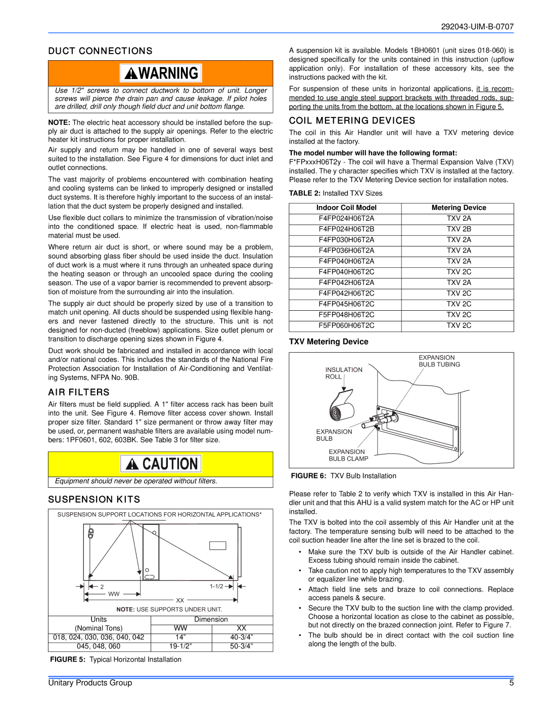
FIGURE 6: TXV Bulb Installation

Please refer to Table 2 to verify which TXV is installed in this Air Han- dler unit and that this AHU is a valid system match for the AC or HP unit installed.

The TXV is bolted into the coil assembly of this Air Handler unit at the factory. The temperature sensing bulb will need to be attached to the coil suction header line after the line set is brazed to the coil.

Make sure the TXV bulb is outside of the Air Handler cabinet. Excess tubing should remain inside the cabinet.

Take caution not to apply high temperatures to the TXV assembly or equalizer line while brazing.

Attach field line sets and braze to coil connections. Replace access panels & secure.

Secure the TXV bulb to the suction line with the clamp provided. Choose a horizontal location as close to the cabinet as possible, but not directly on the brazed connection joint. Refer to Figure 7.

The bulb should be in direct contact with the coil suction line along the length of the bulb.

Unitary Products Group

5

Page 5
Image 5
Coleman F*FP installation manual Duct Connections, AIR Filters, Suspension Kits, Coil Metering Devices

F*FP specifications

The Coleman F*FP, an innovative product from the renowned outdoor gear manufacturer Coleman, represents a significant leap forward in portable lighting solutions. Designed for outdoor enthusiasts, campers, and emergency preparedness, this compact device merges functionality with cutting-edge technology.

One of the standout features of the Coleman F*FP is its impressive brightness, which can easily illuminate small campsites or provide adequate light for activities such as cooking or reading after sunset. With adjustable brightness settings, users can customize the light output according to their specific needs, effectively conserving battery life when full brightness isn’t necessary.

The Coleman F*FP incorporates advanced LED technology, ensuring longevity and efficiency. Unlike traditional incandescent bulbs, the LEDs offer a much longer lifespan and consume significantly less power, making them an ideal choice for outdoor use where access to electricity may be limited. This energy-efficient design makes the F*FP not only cost-effective but also environmentally friendly.

Portability is another key characteristic of the Coleman F*FP. The device is lightweight and compact, making it easy to pack and transport, whether you're heading on a weekend camping trip or preparing for an emergency situation. It typically features a built-in handle or a hook for easy hanging, allowing for versatile placement in tents, trees, or outdoor structures.

Durability is paramount when it comes to outdoor equipment, and the Coleman F*FP does not disappoint. Constructed with weather-resistant materials, it can withstand various environmental conditions, from rain to dust, ensuring reliable performance and longevity. This rugged construction makes it a trustworthy companion for any outdoor adventure.

The F*FP also includes user-friendly features such as easy-to-navigate controls and battery indicators. Some models may offer rechargeable options, reducing the need for disposable batteries and enhancing sustainability.

In summary, the Coleman F*FP stands out in the realm of outdoor lighting solutions. Its impressive brightness, energy-efficient LED technology, portability, and durable construction make it an essential tool for adventurers and a sensible choice for emergency preparedness. With the Coleman F*FP in tow, users can enjoy peace of mind and a well-lit experience in the great outdoors.