292043-UIM-B-0707

LOW VOLTAGE CONTROL CONNECTION

The 24 volt power supply is provided by an internally wired low voltage transformer which is standard on all models. However, if the unit is con- nected to a 208 volt power supply the low voltage transformer must be rewired to the 208 volt tap. See the unit wiring label.

Field supplied low voltage wiring can exit the unit on the top right hand corner or the right hand side panel (see Fig. 5, item K).

Install a 7/8" plastic bushing in the selected hole and keep low voltage wiring as short as possible inside the control box.

The field wiring is to be connected at the screw terminals of the control board. Refer to Figure’s 12 and 13.

NOTE: All wiring must comply with local and national electrical code requirements. Read and heed all unit caution labels.

NOTE: It is possible to vary the amount of electric heat turned on during the defrost cycle of a heat pump. Standard wiring will only bring on 5 KW of electric heat during defrost see Table 6 and Figures 12 and 13 for alternate staging.

LINE POWER CONNECTIONS

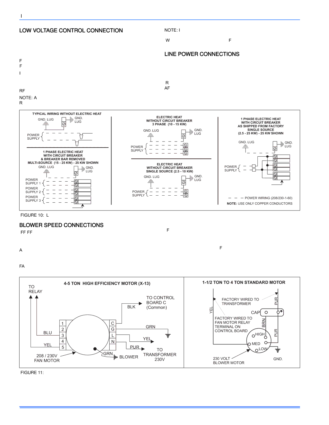
Power may be brought into the unit through the supply air end of the unit (top when unit is vertical) or the left side panel. Use the hole appro- priate to the unit's orientation in each installation to bring conduit from the disconnect. The power lead conduit should be terminated at the electrical control box. Refer to Tables 4, 8 & 10 for wire requirements. Also see Figure 10.

TYPICAL WIRING WITHOUT ELECTRIC HEAT


GND.


ELECTRIC HEAT


1 PHASE ELECTRIC HEAT


GND. LUG


WITHOUT CIRCUIT BREAKER


LUG


WITH CIRCUIT BREAKER


3 PHASE (10 - 15 KW)


AS SHIPPED FROM FACTORY


GND. LUG

GND.

SINGLE SOURCE


(2.5 - 25 KW) - 25 KW SHOWN


POWER


LUG


SUPPLY


GND. LUG

GND.


POWER


LUG

1 PHASE ELECTRIC HEAT


SUPPLY


WITH CIRCUIT BREAKER


& BREAKER BAR REMOVED


MULTI-SOURCE (15 - 25 KW) - 25 KW SHOWN

ELECTRIC HEAT


GND. LUG


GND.

WITHOUT CIRCUIT BREAKER


POWER


LUG

SINGLE SOURCE (2.5 - 10 KW)


SUPPLY


GND. LUG

GND.


POWER


LUG


SUPPLY 1


POWER


SUPPLY 2


POWER


POWER


SUPPLY


POWER WIRING (208/230-1-60)


SUPPLY 3


NOTE: USE ONLY COPPER CONDUCTORS


FIGURE 10: Line Power Connections

BLOWER SPEED CONNECTIONS

Except for F4FP045, which has a 4-speed motor, and F5FP* which has a 5-speed high efficiency X-13 motor, all air handlers contain three speed blower motors which are pre-wired to the control board.

Adjust blower motor speed to provide airflow within the minimum and maximum limits approved for evaporator coil, electric heat and outdoor unit. Speed tap adjustments are made at the motor terminal block, See Figure 11. Airflow data is shown in Tables 6 and 11.

Higher efficiencies will be obtained if the indoor air volume is as high as possible provided the CFM does not exceed limitations and the sound level is not objectionable.

Connect motor wires to motor speed tap receptacle for speed desired. See wiring label for motor wiring details. See Figure 11.

The unit control is designed for the addition of a two speed fan kit. See accessory kit for details.

4-5 TON HIGH EFFICIENCY MOTOR (X-13)

TO

RELAY


TO CONTROL


BOARD C


BLK

(Common)


1


C


GRN


BLU

2


G


3


L


YEL


YEL

4


N


PUR


5


TO


GRN


208 / 230V


TRANSFORMER


BLOWER


230V


FAN MOTOR


FIGURE 11: Blower Speed Connections


1-1/2 TON TO 4 TON STANDARD MOTOR


FACTORY WIRED TO


PUR

YEL

TRANSFORMER


CAP


FACTORY WIRED TO

BRN


FAN MOTOR RELAY


TERMINAL ON


PUR


CONTROL BOARD

HIGH


MED


LOW


230 VOLT


GND.


BLOWER MOTOR


8

Unitary Products Group

Page 8
Image 8
Coleman F*FP installation manual LOW Voltage Control Connection, Line Power Connections, Blower Speed Connections

F*FP specifications

The Coleman F*FP, an innovative product from the renowned outdoor gear manufacturer Coleman, represents a significant leap forward in portable lighting solutions. Designed for outdoor enthusiasts, campers, and emergency preparedness, this compact device merges functionality with cutting-edge technology.

One of the standout features of the Coleman F*FP is its impressive brightness, which can easily illuminate small campsites or provide adequate light for activities such as cooking or reading after sunset. With adjustable brightness settings, users can customize the light output according to their specific needs, effectively conserving battery life when full brightness isn’t necessary.

The Coleman F*FP incorporates advanced LED technology, ensuring longevity and efficiency. Unlike traditional incandescent bulbs, the LEDs offer a much longer lifespan and consume significantly less power, making them an ideal choice for outdoor use where access to electricity may be limited. This energy-efficient design makes the F*FP not only cost-effective but also environmentally friendly.

Portability is another key characteristic of the Coleman F*FP. The device is lightweight and compact, making it easy to pack and transport, whether you're heading on a weekend camping trip or preparing for an emergency situation. It typically features a built-in handle or a hook for easy hanging, allowing for versatile placement in tents, trees, or outdoor structures.

Durability is paramount when it comes to outdoor equipment, and the Coleman F*FP does not disappoint. Constructed with weather-resistant materials, it can withstand various environmental conditions, from rain to dust, ensuring reliable performance and longevity. This rugged construction makes it a trustworthy companion for any outdoor adventure.

The F*FP also includes user-friendly features such as easy-to-navigate controls and battery indicators. Some models may offer rechargeable options, reducing the need for disposable batteries and enhancing sustainability.

In summary, the Coleman F*FP stands out in the realm of outdoor lighting solutions. Its impressive brightness, energy-efficient LED technology, portability, and durable construction make it an essential tool for adventurers and a sensible choice for emergency preparedness. With the Coleman F*FP in tow, users can enjoy peace of mind and a well-lit experience in the great outdoors.