NOTE
In Class II and Class III and Simultaneous Presence locations, limit upward aiming of fixture to a maximum of 30º above horizontal. Greater upward aiming could lead to excessive dust buildup and dangerous overheating of the dust.
5.Repeat the proceeding steps if a second EVLA12 fixture is to be installed on the ELPS50 power supply enclosure.
6.Proceed to Section C for conduit connection and wiring instructions.
C. Conduit Connection and Wiring
1a. Connect enclosure to properly grounded conduit system, installing conduit sealing fittings as required by Section 501.15 and, if required, 502.15 of the National Electrical Code plus any other applicable codes.
1b. If cable is utilized, a cable sealing fitting must be installed as required by Section 501.15 of the National Electrical Code plus any other applicable codes.
NOTE: Refer to Step 2b, making sure that the “designated disconnect” housing is installed in the system.
![]() WARNING
WARNING
•To avoid explosion, all unused conduit openings must be plugged. Plug must engage a minimum of five full threads. Use PLG plugs supplied with the unit.
•To maintain explosionproof integrity, conduit sealing fittings MUST be installed in each attached conduit run (within eighteen inches of the ELPS50 power supply enclosure in Class I locations).
•To maintain explosionproof integrity in Class I areas, conduit sealing fittings are required on all conduit entrances (within eighteen inches of the ELPS50 power supply enclosure) for all remotely located emergency lighting fixtures.
2.Make all wiring connections following wiring diagram located on power supply battery bracket.
NOTE: Although generally not required, the interior assembly may be removed to facilitate wire pulling. Remove four (4)
|
|
|
| YELLOW - AMARILLO |
|
|
|
|
|
|
|
|
|
|
|
|
|
|
|
|
|
|
|
|
|
|
|
|
|
|
|
|
| ||||||||||
|
|
|
| YELLOW - AMARILLO |
|
|
|
|
|
|
|
|
|
|
|
|
|
|
|
|
|
|
|
|
|
|
|
|
|
|
|
|
| ||||||||||
|
|
|
| BLUE - AZUL |
|
|
|
|
|
|
|
|
|
|
|
|
|
|
|
|
|
|
|
|
|
|
|
|
|
|
|
|
| ||||||||||
|
|
|
| BLUE - AZUL |
|
|
|
|
|
|
|
|
|
|
|
|
|
|
|
|
|
|
|
|
|
|
|
|
|
|
|
|
| ||||||||||
L | - | L+ |
|
|
|
|
|
|
|
|
|
| RED |
|
|
| ORANGE - NARANJA |
|
|
|
|
|
|
|
|
|
|
|
|
|
|
|
| BATTERY | |||||||||
|
|
|
|
|
|
|
|
|
|
|
|
|
|
|
|
|
|
|
|
|
|
|
|
|
|
|
|
|
|
|
|
|
|
|
|
|
|
|
|
| BATERIA | ||
|
|
|
|
|
|
|
|
|
|
|
|
|
|
|
|
|
|
|
|
|
|
|
|
|
|
|
|
|
|
|
|
|
|
|
|
|
|
|
|
| 21G03 | ||
|
|
|
|
|
|
|
|
|
|
|
|
|
|
|
|
|
|
|
|
|
|
|
|
|
|
|
|
|
|
|
|
|
|
|
|
|
|
|
|
|
|
|
|
|
|
|
|
|
|
|
|
|
|
|
|
|
|
|
|
|
|
|
| BROWN - CAFE |
|
|
|
|
|
|
|
|
|
|
|
|
|
|
|
|
|
|
|
|
|
| |
|
|
|
|
|
|
|
|
|
|
|
|
|
|
|
|
|
|
|
| BLACK - NEGRO |
|
|
|
|
|
|
|
|
|
|
|
|
|
|
|
|
|
|
|
|
|
| |
|
|
|
|
|
|
|
|
|
|
|
|
|
|
|
|
|
|
|
| WHITE - BLANCO |
|
|
|
|
|
|
|
|
|
|
|
|
|
|
|
|
|
|
|
|
|
| |
|
|
|
|
|
|
|
|
|
|
|
|
|
|
|
|
|
|
|
|
|
|
|
|
|
|
|
|
|
|
|
|
|
|
|
|
|
|
|
|
|
|
|
|
|
|
|
|
|
|
|
|
|
|
|
|
|
|
|
|
|
|
|
|
| 1 | 2 | 3 | 4 | 5 |
|
| 6 | 7 | 8 | 9 | NEGRO | - ROJO |
| |||||||||
|
|
|
|
|
|
|
|
|
|
|
|
|
|
|
|
|
|
|
|
|
|
|
| ||||||||||||||||||||
|
|
|
|
|
|
|
|
|
|
|
|
|
|
|
|
|
|
|
|
|
|
|
|
|
|
|
|
|
|
|
|
|
|
|
|
|
|
|
|
|
| ||
|
|
|
|
|
|
|
|
|
|
|
|
|
|
|
|
|
|
|
|
| GRD | COM | 120 | 220 | 277 |
|
|
|
|
|
|
|
|
|
| ||||||||
|
|
|
|
|
|
|
|
|
|
|
|
|
|
|
|
| TRANSFORMER |
|
|
|
|
| 127 | 240 |
|
|
|
|
|
|
|
|
|
|
|
| BLACK- | RED |
| ||||
|
|
|
|
|
|
|
|
|
|
|
|
|
|
|
|
| MAIN CHARGER |
|
|
|
|
|
|
|
|
|
|
|
|
|
|
|
|
|
|
|
|
|
|
|
| ||
|
|
|
|
|
|
|
|
|
|
|
|
|
|
|
|
| TRANSFORMADOR |
| TERMINAL BLOCK |
|
|
|
|
|
|
|
|
|
|
|
|
|
|
|
|
| |||||||
|
|
|
|
|
|
|
|
|
|
|
|
|
|
|
|
|
| BLOCK DE TERMINALES |
|
|
|
|
|
|
|
|
|
|
|
|
|
|
| ||||||||||
|
|
|
|
|
|
|
|
|
|
|
|
|
|
|
|
| PRINCIPAL DE |
|
|
|
|
| EVLA12'S |
|
|
|
|
|
|
| |||||||||||||
|
|
|
|
|
|
|
|
|
|
|
|
|
|
|
|
|
|
|
|
|
|
|
|
|
|
|
|
|
|
|
|
|
|
|
|
| |||||||
|
|
|
|
|
|
|
|
|
|
|
|
|
|
|
|
| CARGA |
|
|
|
|
|
|
|
|
|
|
|
|
|
|
|
|
|
|
|
| ||||||
TEST SWITCH |
|
|
|
|
|
|
|
|
|
|
|
|
|
|
|
|
|
|
|
|
|
|
|
|
|
|
|
|
|
|
|
|
|
|
|
|
|
|
|
| |||
BUTON DE PRUEBA |
|
|
|
|
|
|
|
|
|
|
|
|
|
|
|
|
|
|
|
|
|
|
|
|
|
|
| BATTERY DISCONNECT | |||||||||||||||
|
|
|
|
|
|
|
|
|
|
|
|
|
|
|
|
|
|
|
|
|
|
|
|
|
|
|
|
|
|
|
|
|
|
|
|
| |||||||
|
|
|
|
|
|
|
| PILOT LIGHT |
|
|
|
|
|
|
|
|
|
|
|
|
|
|
|
|
|
|
|
|
|
| SWITCH |
|
|
| |||||||||
|
|
|
| LAMPARA PILOTO |
|
|
|
|
|
|
|
|
|
|
|
|
|
|
|
|
|
|
|
|
|
| INTERRUPTOR |
|
|
| |||||||||||||
|
|
|
|
|
|
|
|
|
|
|
|
|
|
|
|
|
|
|
|
|
|
|
|
|
|
|
|
|
|
|
|
|
|
|
|
| DESCONECTADOR |
|
| ||||
|
|
|
|
|
|
|
|
|
|
|
|
|
|
|
|
|
|
|
|
|
|
|
|
|
|
|
|
|
|
|
|
|
|
|
|
| DE BATERIA |
|
|
| |||
|
|
|
|
|
|
|
|
|
| 1 = GRD |
|
|
|
| 4 = 220/240 |
|
|
|
|
|
|
|
| 7 = L - |
|
|
|
|
| ||||||||||||||
|
|
|
|
|
|
|
|
|
| 2 = COM |
|
|
|
| 5 = 277 |
|
|
|
|
|
|
|
|
|
|
| 8 = BATT + |
|
|
| |||||||||||||
|
|
|
| 3 = 120 |
|
|
|
|
| 6 = L + |
|
|
|
|
|
|
|
|
|
| 9 = BATT - |
|
|
| |||||||||||||||||||
Figure 3. Wiring Diagram
![]() WARNING
WARNING
•To avoid explosion or personal injury, all electrical power must be turned OFF before and during installation and maintenance and installation area must be free of hazardous atmospheres.
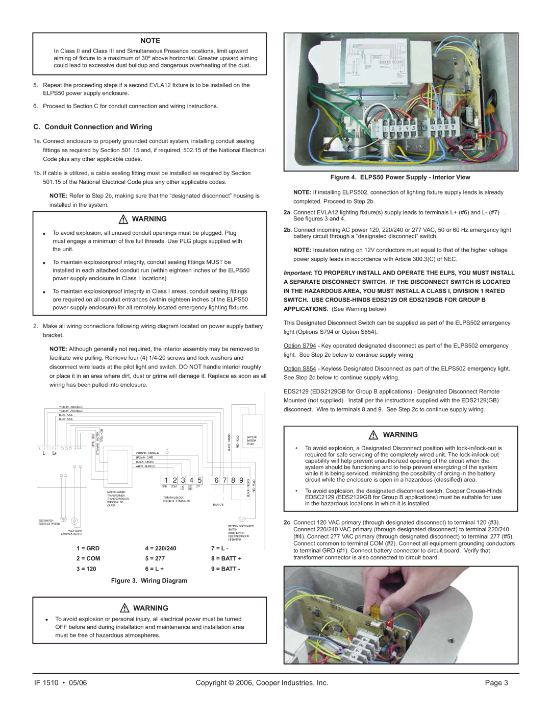
Figure 4. ELPS50 Power Supply - Interior View
NOTE: If installing ELPS502, connection of lighting fixture supply leads is already
completed. Proceed to Step 2b.
2a. Connect EVLA12 lighting fixture(s) supply leads to terminals L+ (#6) and L- (#7) . See figures 3 and 4.
2b. Connect incoming AC power 120, 220/240 or 277 VAC, 50 or 60 Hz emergency light battery circuit through a “designated disconnect” switch.
NOTE: Insulation rating on 12V conductors must equal to that of the higher voltage
power supply leads in accordance with Article 300.3(C) of NEC.
Important: TO PROPERLY INSTALL AND OPERATE THE ELPS, YOU MUST INSTALL A SEPARATE DISCONNECT SWITCH. IF THE DISCONNECT SWITCH IS LOCATED IN THE HAZARDOUS AREA, YOU MUST INSTALL A CLASS I, DIVISION 1 RATED SWITCH. USE
This Designated Disconnect Switch can be supplied as part of the ELPS502 emergency
light (Options S794 or Option S854).
Option S794 - Key operated designated disconnect as part of the ELPS502 emergency
light. See Step 2c below to continue supply wiring
Option S854 - Keyless Designated Disconnect as part of the ELPS502 emergency light.
See Step 2c below to continue supply wiring.
EDS2129 (EDS2129GB for Group B applications) - Designated Disconnect Remote
Mounted (not supplied). Install per the instructions supplied with the EDS2129(GB)
disconnect. Wire to terminals 8 and 9. See Step 2c to continue supply wiring.
![]() WARNING
WARNING
•To avoid explosion, a Designated Disconnect position with
•To avoid explosion, the designated disconnect switch, Cooper
2c. Connect 120 VAC primary (through designated disconnect) to terminal 120 (#3). Connect 220/240 VAC primary (through designated disconnect) to terminal 220/240 (#4). Connect 277 VAC primary (through designated disconnect) to terminal 277 (#5). Connect common to terminal COM (#2). Connect all equipment grounding conductors to terminal GRD (#1). Connect battery connector to circuit board. Verify that transformer connector is also connected to circuit board.
IF 1510 • 05/06 | Copyright © 2006, Cooper Industries, Inc. | Page 3 |