REPLACEMENT CIRCUIT BOARD & BATTERY KIT
ELPS-K50 KIT CONSISTS OF:
(1)Circuit Board & Charger Assembly with Mounting Bracket
(1)IF-
(1)Sealed
(1)2 Volt LED for Pilot Light
(1)CID101 Corrosion Inhibitor Device
This kit includes a new, LED indicating lamp that gives a visual status of the unit. Details indicating LED logic is given below:
NOTE
ELPS series emergency light fixtures were
| No Light | AC power is removed from circuit |
• | Steady Light (No blinks) | Fully Charged |
• | Light Blinks Once | Charging |
• - • | Light Blinks Twice | Battery Failure |
• - • - • | Light Blinks Three Times | Circuit Failure |
Immediately after supply power is initiated the indicating lamp will blink/pulse to indicate that the unit is charging. Once installed with supply power, the ELPS requires 72 hours to charge the battery. Once the unit has completed charging, the indicating light will stop blinking and go to steady. Every six months, the unit will automatically perform a 90- minute battery discharge test.
At the completion of the test, if it is determined not to have met the 90 minute requirement, the indicating lamp will display circuit failure (3 blinks). At any time, if the battery connection is not adequate the indicating lamp will display a battery failure (2 blinks).
![]() WARNING
WARNING
To prevent injury from electric shock, all power must be removed from the fixture during maintenance.
![]() WARNING
WARNING
Even after disconnect, batteries will still be live. To prevent electrical shock and explosion, take extra care not to touch leads together or to ground.
MAINTENANCE
![]() WARNING
WARNING
To avoid explosion always disconnect primary power source using designated disconnect switch before opening enclosure for inspection or service.
1.Conduct periodic testing in accordance with local authority and Periodic Testing section of these instructions.
2.Clean fixture lens and exterior surfaces periodically. We recommend every three months or more frequently if appropriate.
3.Frequent interior inspection should be made. A schedule for maintenance check should be determined by the environment and frequency of use. It is recommended that it should be at least once a year.
4.Perform visual, electrical, and mechanical checks on all components on a regular basis.
•Visually check for undue heating evidenced by discoloration of wires or other components, damage or worn parts, or leakage evidence by
water or corrosion in the interior.
•Electrically check to make sure that all connections are clean and tight.
•Mechanically check that all parts are properly assembled.
5.Do not attempt field replacement or repair of ELPS50 Power Supply cover gasket. Instead, remove damaged gasket and continue to use cover without gasket. This will assure safety for use in Class I and Class II hazardous (classified) locations. However, the enclosure will not be rain tight.
![]() CAUTION
CAUTION
To avoid explosion, clean both flat joint surfaces of body and cover before closing. Dirt or foreign material must not accumulate on flat joint surfaces. Surfaces must seat fully against each other to provide a proper explosion proof seal.
BREATHER AND DRAIN
ELPS50 power supply enclose is provided with breather and drain. Refer to Installation and Maintenance Information
![]() IMPORTANT
IMPORTANT
A DESIGNATED DISCONNECT SWITCH IS REQUIRED FOR SAFETY, TO POWER THE ELPS502 EMERGENCY LIGHT SYSTEM AND CHARGE THE BATTERIES.
To avoid explosion, a Designated Disconnect switch with
Units supplied with option S794 or Option S854 already have a disconnect switch installed on the enclosure. Standard units require a remote disconnect switch. If the switch is also located in a hazardous area, you must install a Class 1, Div. 1, rated switch. Use
|
|
|
| YELLOW - AMARILLO |
|
|
|
|
|
|
|
|
|
|
|
|
|
|
|
|
|
|
|
|
|
|
|
|
|
|
|
|
| ||||
|
|
|
| YELLOW - AMARILLO |
|
|
|
|
|
|
|
|
|
|
|
|
|
|
|
|
|
|
|
|
|
|
|
|
|
|
|
|
| ||||
|
|
|
| BLUE - AZUL |
|
|
|
|
|
|
|
|
|
|
|
|
|
|
|
|
|
|
|
|
|
|
|
|
|
|
|
|
| ||||
|
|
|
| BLUE - AZUL |
|
|
|
|
|
|
|
|
|
|
|
|
|
|
|
|
|
|
|
|
|
|
|
|
|
|
|
|
| ||||
L | - | L+ |
|
|
|
|
| RED | ORANGE - NARANJA |
|
|
|
|
|
|
|
|
|
|
|
|
|
|
| BATTERY | ||||||||||||
|
|
|
|
|
|
|
|
|
|
|
|
|
|
|
|
|
|
|
|
|
|
|
|
|
|
|
|
|
|
|
|
|
|
| BATERIA | ||
|
|
|
|
|
|
|
|
|
|
|
|
|
|
|
|
|
|
|
|
|
|
|
|
|
|
|
|
|
|
|
|
|
|
| 21G03 | ||
|
|
|
|
|
|
|
|
|
|
|
|
|
|
|
|
|
|
|
|
|
|
|
|
|
|
|
|
|
|
|
|
|
|
|
|
|
|
|
|
|
|
|
|
|
|
|
|
|
|
|
|
| BROWN - CAFE |
|
|
|
|
|
|
|
|
|
|
|
|
|
|
|
|
|
|
|
|
| |
|
|
|
|
|
|
|
|
|
|
|
|
|
|
| BLACK - NEGRO |
|
|
|
|
|
|
|
|
|
|
|
|
|
|
|
|
|
|
|
|
| |
|
|
|
|
|
|
|
|
|
|
|
|
|
|
| WHITE - BLANCO |
|
|
|
|
|
|
|
|
|
|
|
|
|
|
|
|
|
|
|
|
| |
|
|
|
|
|
|
|
|
|
|
|
|
|
|
|
|
|
|
|
|
|
|
|
|
|
|
|
|
|
|
|
|
|
|
|
|
|
|
|
|
|
|
|
|
|
|
|
|
|
|
|
|
|
| 1 | 2 | 3 | 4 | 5 |
|
| 6 | 7 | 8 | 9 | NEGRO | - ROJO |
| ||||||||
|
|
|
|
|
|
|
|
|
|
|
|
|
|
|
|
|
|
| |||||||||||||||||||
|
|
|
|
|
|
|
|
|
|
|
|
|
|
|
|
|
|
|
|
|
|
|
|
|
|
|
|
|
|
|
|
|
|
|
| ||
|
|
|
|
|
|
|
|
|
|
|
|
|
|
|
| GRD | COM | 120 | 220 | 277 |
|
|
|
|
|
|
|
|
| ||||||||
|
|
|
|
|
|
|
|
|
|
|
| TRANSFORMER |
|
|
|
|
| 127 | 240 |
|
|
|
|
|
|
|
|
|
|
| BLACK- | RED |
| ||||
|
|
|
|
|
|
|
|
|
|
|
| MAIN CHARGER |
|
|
|
|
|
|
|
|
|
|
|
|
|
|
|
|
|
|
|
|
|
|
| ||
|
|
|
|
|
|
|
|
|
|
|
| TRANSFORMADOR |
| TERMINAL BLOCK |
|
|
|
|
|
|
|
|
|
|
|
|
|
|
|
| |||||||
|
|
|
|
|
|
|
|
|
|
|
| PRINCIPAL DE |
| BLOCK DE TERMINALES |
|
|
|
| EVLA12'S |
|
|
|
|
|
| ||||||||||||
|
|
|
|
|
|
|
|
|
|
|
|
|
|
|
|
|
|
|
|
|
|
|
|
|
|
|
|
|
|
| |||||||
|
|
|
|
|
|
|
|
|
|
|
| CARGA |
|
|
|
|
|
|
|
|
|
|
|
|
|
|
|
|
|
|
| ||||||
|
|
|
|
|
|
|
|
|
|
|
| 1 = GRD | 4 = 220/240 |
| 7 = L - |
|
|
|
|
|
|
|
|
|
|
|
|
|
| ||||||||
TEST SWITCH |
|
|
|
|
|
|
|
|
|
|
|
|
|
|
|
|
|
|
|
|
|
| |||||||||||||||
BUTON DE PRUEBA |
|
|
|
|
|
|
|
|
|
|
|
|
|
| BATTERY DISCONNECT | ||||||||||||||||||||||
|
|
|
|
|
|
|
|
|
|
|
| 2 = COM | 5 = 277 |
|
|
| 8 = BATT + |
|
|
|
| ||||||||||||||||
|
|
|
|
|
|
|
|
|
|
|
|
|
|
|
|
|
|
| INTERRUPTOR |
|
|
| |||||||||||||||
|
|
|
|
| PILOT LIGHT |
|
|
|
|
|
|
|
|
|
|
|
|
|
|
|
|
|
|
|
|
|
|
| SWITCH |
|
|
| |||||
|
|
|
|
|
|
|
|
|
|
|
|
|
|
|
|
|
|
|
|
|
|
|
|
|
|
|
|
|
|
|
|
|
| ||||
|
|
|
| LAMPARA PILOTO |
|
|
|
|
|
|
|
|
|
|
|
|
|
|
|
|
|
|
|
|
|
|
| DESCONECTADOR |
|
| |||||||
|
|
|
|
|
|
|
|
|
|
| 3 = 120 |
| 6 = L + |
| 9 = BATT - |
|
|
|
|
|
| ||||||||||||||||
|
|
|
|
|
|
|
|
|
|
|
|
|
|
|
|
| DE BATERIA |
|
|
| |||||||||||||||||
Figure 7. Wiring Diagram
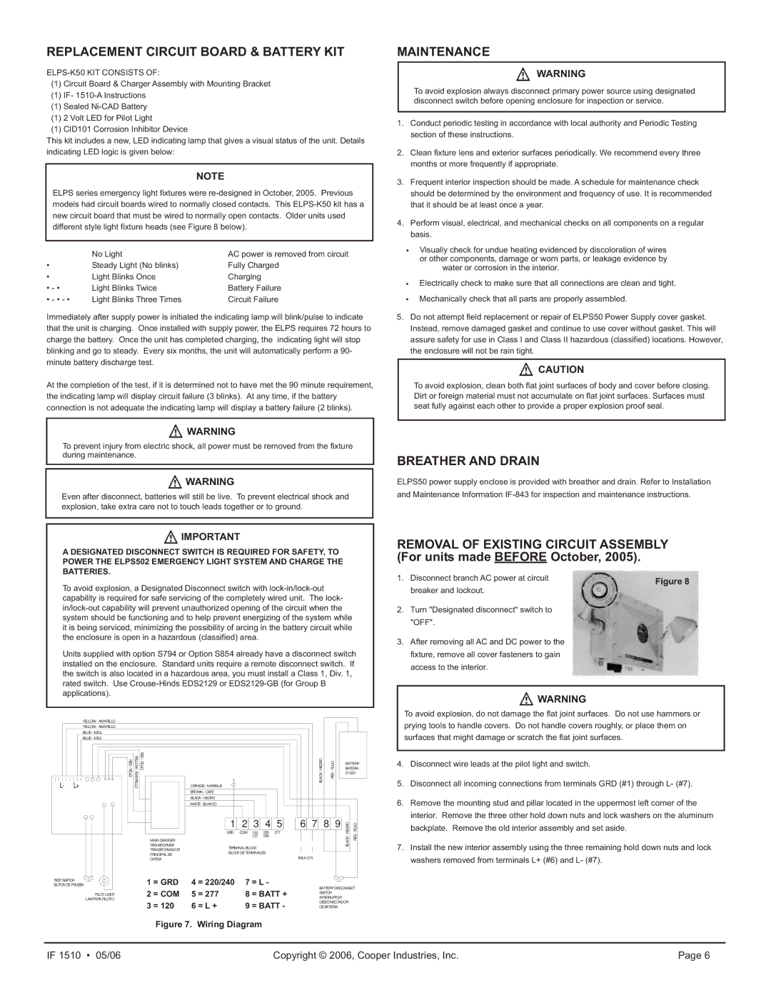
REMOVAL OF EXISTING CIRCUIT ASSEMBLY (For units made BEFORE October, 2005).
1. Disconnect branch AC power at circuit | Figure 8 | |
breaker and lockout. | ||
|
2.Turn "Designated disconnect" switch to "OFF".
3.After removing all AC and DC power to the fixture, remove all cover fasteners to gain access to the interior.
![]() WARNING
WARNING
To avoid explosion, do not damage the flat joint surfaces. Do not use hammers or prying tools to handle covers. Do not handle covers roughly, or place them on surfaces that might damage or scratch the flat joint surfaces.
4.Disconnect wire leads at the pilot light and switch.
5.Disconnect all incoming connections from terminals GRD (#1) through L- (#7).
6.Remove the mounting stud and pillar located in the uppermost left corner of the interior. Remove the three other hold down nuts and lock washers on the aluminum backplate. Remove the old interior assembly and set aside.
7.Install the new interior assembly using the three remaining hold down nuts and lock washers removed from terminals L+ (#6) and L- (#7).
IF 1510 • 05/06 | Copyright © 2006, Cooper Industries, Inc. | Page 6 |