8.Replace the old incandescent lamp (or old LED) in the pilot light and replace with the new, 2 volt LED supplied with the new interior assembly.
9.Make all incoming wiring connections following the wiring diagram located in the new assembly (also see Figure 7) and
![]() NOTE
NOTE
Older circuit boards are wired to normally closed contacts. Replacement circuit boards must be wired to normally open contacts.
10.Install the CID101 corrosion prohibitor device included with kit by pealing back the protective covering to expose the adhesive. Install the CID101 in upper portion inside enclosure wall.
REMOVAL OF EXISTING CIRCUIT ASSEMBLY (For units made AFTER October, 2005).
1. | Disconnect branch AC power at circuit |
|
| breaker and lockout. |
|
2. | Turn "Designated disconnect" switch to |
|
| "OFF". |
|
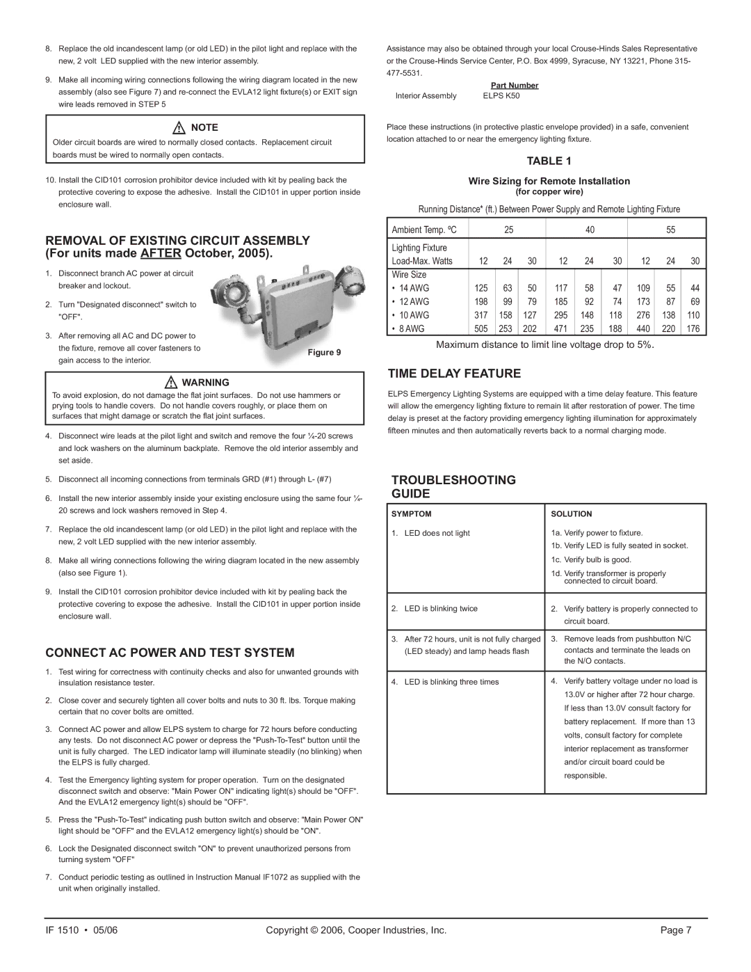
3. | After removing all AC and DC power to |
|
| the fixture, remove all cover fasteners to | Figure 9 |
|
|
gain access to the interior.
![]() WARNING
WARNING
To avoid explosion, do not damage the flat joint surfaces. Do not use hammers or prying tools to handle covers. Do not handle covers roughly, or place them on surfaces that might damage or scratch the flat joint surfaces.
4.Disconnect wire leads at the pilot light and switch and remove the four
5.Disconnect all incoming connections from terminals GRD (#1) through L- (#7)
6.Install the new interior assembly inside your existing enclosure using the same four ¼- 20 screws and lock washers removed in Step 4.
7.Replace the old incandescent lamp (or old LED) in the pilot light and replace with the new, 2 volt LED supplied with the new interior assembly.
8.Make all wiring connections following the wiring diagram located in the new assembly (also see Figure 1).
9.Install the CID101 corrosion prohibitor device included with kit by pealing back the protective covering to expose the adhesive. Install the CID101 in upper portion inside enclosure wall.
CONNECT AC POWER AND TEST SYSTEM
1.Test wiring for correctness with continuity checks and also for unwanted grounds with insulation resistance tester.
2.Close cover and securely tighten all cover bolts and nuts to 30 ft. lbs. Torque making certain that no cover bolts are omitted.
3.Connect AC power and allow ELPS system to charge for 72 hours before conducting any tests. Do not disconnect AC power or depress the
4.Test the Emergency lighting system for proper operation. Turn on the designated disconnect switch and observe: "Main Power ON" indicating light(s) should be "OFF". And the EVLA12 emergency light(s) should be "OFF".
5.Press the
6.Lock the Designated disconnect switch "ON" to prevent unauthorized persons from turning system "OFF"
7.Conduct periodic testing as outlined in Instruction Manual IF1072 as supplied with the unit when originally installed.
Assistance may also be obtained through your local
| Part Number |
Interior Assembly | ELPS K50 |
Place these instructions (in protective plastic envelope provided) in a safe, convenient location attached to or near the emergency lighting fixture.
TABLE 1
Wire Sizing for Remote Installation
(for copper wire)
Running Distance* (ft.) Between Power Supply and Remote Lighting Fixture
Ambient Temp. ºC |
| 25 |
|
| 40 |
|
| 55 |
|
|
|
|
|
|
|
|
|
|
|
Lighting Fixture |
|
|
|
|
|
|
|
|
|
12 | 24 | 30 | 12 | 24 | 30 | 12 | 24 | 30 | |
Wire Size |
|
|
|
|
|
|
|
|
|
• 14 AWG | 125 | 63 | 50 | 117 | 58 | 47 | 109 | 55 | 44 |
• 12 AWG | 198 | 99 | 79 | 185 | 92 | 74 | 173 | 87 | 69 |
• 10 AWG | 317 | 158 | 127 | 295 | 148 | 118 | 276 | 138 | 110 |
• 8 AWG | 505 | 253 | 202 | 471 | 235 | 188 | 440 | 220 | 176 |
Maximum distance to limit line voltage drop to 5%.
TIME DELAY FEATURE
ELPS Emergency Lighting Systems are equipped with a time delay feature. This feature will allow the emergency lighting fixture to remain lit after restoration of power. The time delay is preset at the factory providing emergency lighting illumination for approximately fifteen minutes and then automatically reverts back to a normal charging mode.
TROUBLESHOOTING
GUIDE
SYMPTOM | SOLUTION | ||
1. | LED does not light | 1a. | Verify power to fixture. |
|
| 1b. | Verify LED is fully seated in socket. |
|
| 1c. | Verify bulb is good. |
|
| 1d. | Verify transformer is properly |
|
|
| connected to circuit board. |
|
|
|
|
2. | LED is blinking twice | 2. | Verify battery is properly connected to |
|
|
| circuit board. |
|
|
|
|
3. | After 72 hours, unit is not fully charged | 3. | Remove leads from pushbutton N/C |
| (LED steady) and lamp heads flash |
| contacts and terminate the leads on |
|
|
| the N/O contacts. |
|
|
|
|
4. | LED is blinking three times | 4. | Verify battery voltage under no load is |
|
|
| 13.0V or higher after 72 hour charge. |
|
|
| If less than 13.0V consult factory for |
|
|
| battery replacement. If more than 13 |
|
|
| volts, consult factory for complete |
|
|
| interior replacement as transformer |
|
|
| and/or circuit board could be |
|
|
| responsible. |
|
|
|
|
IF 1510 • 05/06 | Copyright © 2006, Cooper Industries, Inc. | Page 7 |