INSTALLATION
A. Install ELPS502 System or ELPS50 Power Supply
![]() WARNING
WARNING
To avoid electrical shock, electrical power must be turned OFF before and during installation and maintenance.
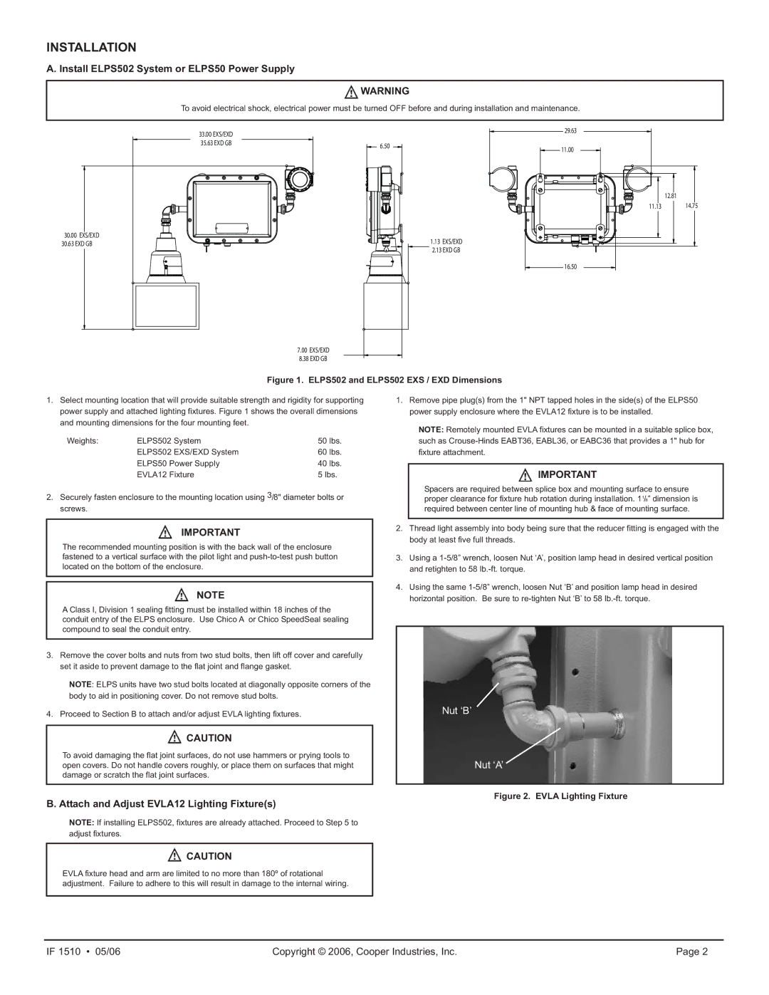
30.00EXS/EXD
30.63EXD GB
33.00 EXS/EXD |
|
35.63 EXD GB | 6.50 |
|
1.13 EXS/EXD
![]() 2.13 EXD GB
2.13 EXD GB
7.00 EXS/EXD
8.38 EXD GB
29.63
11.00
| 12.81 |
11.13 | 14.75 |
16.50 |
|
Figure 1. ELPS502 and ELPS502 EXS / EXD Dimensions
1. Select mounting location that will provide suitable strength and rigidity for supporting | 1. Remove pipe plug(s) from the 1" NPT tapped holes in the side(s) of the ELPS50 |
power supply and attached lighting fixtures. Figure 1 shows the overall dimensions | power supply enclosure where the EVLA12 fixture is to be installed. |
and mounting dimensions for the four mounting feet. | NOTE: Remotely mounted EVLA fixtures can be mounted in a suitable splice box, |
|
Weights: | ELPS502 System | 50 lbs. |
| ELPS502 EXS/EXD System | 60 lbs. |
| ELPS50 Power Supply | 40 lbs. |
| EVLA12 Fixture | 5 lbs. |
2.Securely fasten enclosure to the mounting location using 3/8" diameter bolts or screws.
IMPORTANT
The recommended mounting position is with the back wall of the enclosure fastened to a vertical surface with the pilot light and
NOTE
A Class I, Division 1 sealing fitting must be installed within 18 inches of the conduit entry of the ELPS enclosure. Use Chico A or Chico SpeedSeal sealing compound to seal the conduit entry.
3.Remove the cover bolts and nuts from two stud bolts, then lift off cover and carefully set it aside to prevent damage to the flat joint and flange gasket.
NOTE: ELPS units have two stud bolts located at diagonally opposite corners of the body to aid in positioning cover. Do not remove stud bolts.
4. Proceed to Section B to attach and/or adjust EVLA lighting fixtures.
![]() CAUTION
CAUTION
To avoid damaging the flat joint surfaces, do not use hammers or prying tools to open covers. Do not handle covers roughly, or place them on surfaces that might damage or scratch the flat joint surfaces.
B. Attach and Adjust EVLA12 Lighting Fixture(s)
NOTE: If installing ELPS502, fixtures are already attached. Proceed to Step 5 to adjust fixtures.
![]() CAUTION
CAUTION
such as
![]() IMPORTANT
IMPORTANT
Spacers are required between splice box and mounting surface to ensure proper clearance for fixture hub rotation during installation. 11/8” dimension is required between center line of mounting hub & face of mounting surface.
2.Thread light assembly into body being sure that the reducer fitting is engaged with the body at least five full threads.
3.Using a
4.Using the same
Nut ‘B’
Nut ‘A’
Figure 2. EVLA Lighting Fixture
EVLA fixture head and arm are limited to no more than 180º of rotational adjustment. Failure to adhere to this will result in damage to the internal wiring.
IF 1510 • 05/06 | Copyright © 2006, Cooper Industries, Inc. | Page 2 |