Page 6 of 21WR 3M
− can remotely control the unit and chart, store and print temperature curves ("Monitor Software“).
5 Initial Set-up
WARNING! Risk of injury may occur if vacuum hose is incorrectly
|
| • | connected to the air port (15). |
|
| If the vacuum hose is incorrectly connected, hot air and liquid | |
|
| solder can escape when the desoldering button is depressed and | |
|
| may cause injuries. | |
|
|
| Z Never connect the vacuum hose to the "Air“ port (15)! |
|
|
|
|
|
|
| 1. Carefully unpack the device. |
|
|
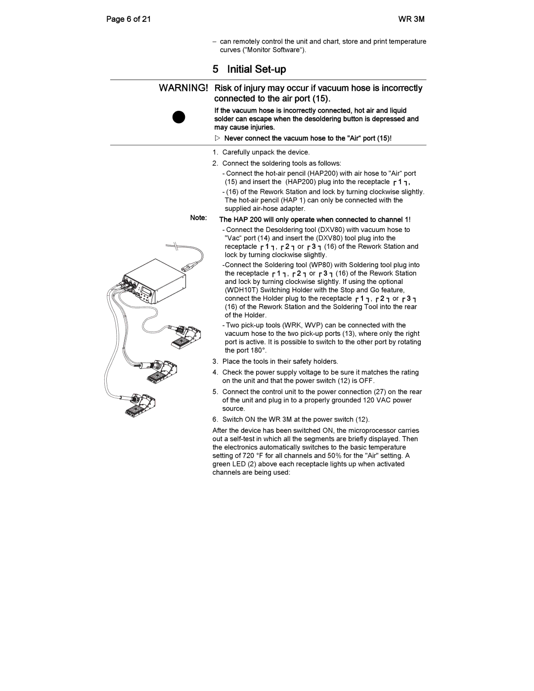
| 2. Connect the soldering tools as follows: |
|
|
| - Connect the |
|
|
| (15) and insert the (HAP200) plug into the receptacle ┌ 1 ┐, |
|
|
| - (16) of the Rework Station and lock by turning clockwise slightly. |
|
|
| The |
|
| Note: | supplied |
|
| ||
|
| The HAP 200 will only operate when connected to channel 1! | |
|
|
| - Connect the Desoldering tool (DXV80) with vacuum hose to |
|
|
| "Vac“ port (14) and insert the (DXV80) tool plug into the |
|
|
| receptacle ┌ 1 ┐, ┌ 2 ┐ or ┌ 3 ┐ (16) of the Rework Station and |
|
|
| lock by turning clockwise slightly. |
(16)of the Rework Station and the Soldering Tool into the rear of the Holder.
-Two
vacuum hose to the two
3.Place the tools in their safety holders.
4.Check the power supply voltage to be sure it matches the rating on the unit and that the power switch (12) is OFF.
5.Connect the control unit to the power connection (27) on the rear
of the unit and plug in to a properly grounded 120 VAC power source.
6. Switch ON the WR 3M at the power switch (12).
After the device has been switched ON, the microprocessor carries out a