SLR • SLC • SLD OPERATOR INSTALLATION GUIDE
CONTROL BOARD ADJUSTMENTS
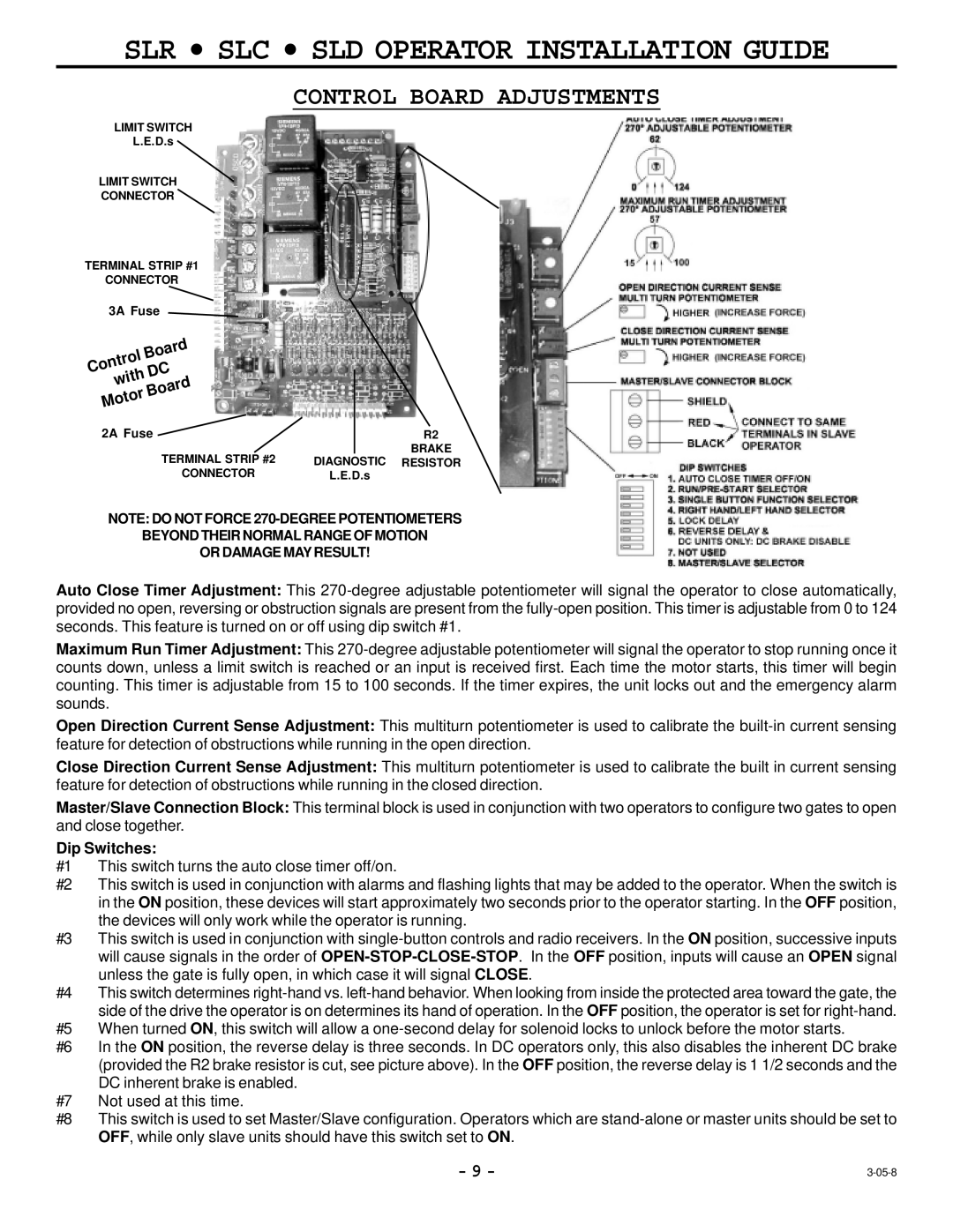
LIMIT SWITCH
L.E.D.s
LIMIT SWITCH
CONNECTOR
TERMINAL STRIP #1
CONNECTOR
3A Fuse |
| |
Board |
| |
Control | DC |
|
with |
| |
|
| |
Board |
| |
Motor |
|
|
2A Fuse | R2 | |
| TERMINAL STRIP #2 | BRAKE |
| DIAGNOSTIC RESISTOR | |
| CONNECTOR | L.E.D.s |
NOTE: DO NOT FORCE
BEYOND THEIR NORMAL RANGE OF MOTION
OR DAMAGE MAY RESULT!
Auto Close Timer Adjustment: This
Maximum Run Timer Adjustment: This
Open Direction Current Sense Adjustment: This multiturn potentiometer is used to calibrate the
Close Direction Current Sense Adjustment: This multiturn potentiometer is used to calibrate the built in current sensing feature for detection of obstructions while running in the closed direction.
Master/Slave Connection Block: This terminal block is used in conjunction with two operators to configure two gates to open and close together.
Dip Switches:
#1 This switch turns the auto close timer off/on.
#2 This switch is used in conjunction with alarms and flashing lights that may be added to the operator. When the switch is in the ON position, these devices will start approximately two seconds prior to the operator starting. In the OFF position, the devices will only work while the operator is running.
#3 This switch is used in conjunction with
#4 This switch determines
#5 When turned ON, this switch will allow a
#6 In the ON position, the reverse delay is three seconds. In DC operators only, this also disables the inherent DC brake (provided the R2 brake resistor is cut, see picture above). In the OFF position, the reverse delay is 1 1/2 seconds and the DC inherent brake is enabled.
#7 Not used at this time.
#8 This switch is used to set Master/Slave configuration. Operators which are
- 9 - |