ATTACHING THE ROUTER Fig. 4
TO THE TABLE
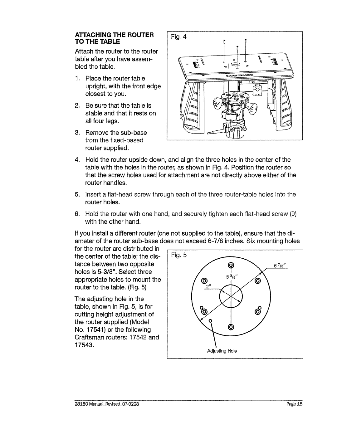
Attach the router to the router table after you have assem- bled the table.
2_
.
Place the router table upright, with the front edge closest to you.
Be sure that the table is stable and that it rests on all four legs,
Remove the
4_ Hold the router upside down, and align the three holes in the center of the table with the holes in the router, as shown in Fig° 4. Position the router so that the screw holes used for attachment are not directly above either of the router handles.
5.Insert a
6_ Hold the router with one hand, and securely tighten each
If you install a different router (one not supplied to the table), ensure that the di- ameter of the router
the center | of the table; the | dis- | Fig, 5 | |||
tance | between | two | opposite | 6 71e" | ||
holes is |
| |||||
appropriate holes to mount the |
| |||||
router to the table. (Fig, 5) |
|
| ||||
The adjusting hole in the |
|
| ||||
table, shown in Fig. 5, is for |
| |||||
cutting | height | adjustment | of |
| ||
the router | supplied | (Model |
|
| ||
No. 17541) or the following |
|
| ||||
Craftsman | reuters: | 17542 | and |
| ||
17543. |
|
|
|
|
|
|
|
|
|
|
|
| Adjusting Hole |
28180 | Page 15 |