BASIC AIR COMPRESSOR | COMPONENTS |
| A |
|
|
| |
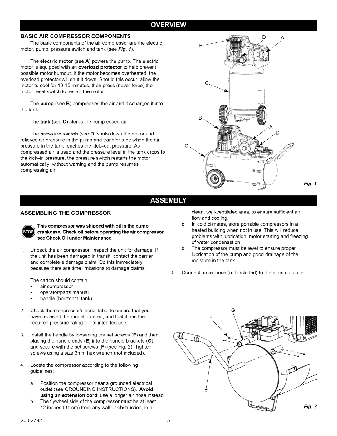
The basic components of the air compressor are the electric | i | , | |
| B | ||
motor, pump, pressure switch and tank (see Fig. 1). | i | D | |
|
|
| |
The electric motor (see A) powers the pump. The electric motor is equipped with an overload protector to help prevent possible motor burnout. If the motor becomes overheated, the overload protector will shut it down. Should this occur, allow the motor to cool for
The pump (see B) compresses the air and discharges it into the tank.
The tank (see C) stores the compressed air.
The pressure switch (see D) shuts down the motor and relieves air pressure in the pump and transfer tube when the air pressure in the tank reaches the
ASSEMBLING THE COMPRESSOR
This compressor was shipped with oil in the pump
crankcase. Check oil before operating the air compressor, see Check Oil under Maintenance.
1.Unpack the air compressor. Inspect the unit for damage. If the unit has been damaged in transit, contact the carrier and complete a damage claim. Do this immediately because there are time limitations to damage claims.
The carton should contain:
•air compressor
•operator/parts manual
•handle (horizontal tank)
Fig. 1
clean,
c.In cold climates, store portable compressors in a heated building when not in use. This wilt reduce problems with lubrication, motor starting and freezing of water condensation.
d.The compressor must be level to ensure proper lubrication of the pump and good drainage of the moisture in the tank.
5.Connect an air hose (not included) to the manifold outlet.
2.Check the compressor's serial label to ensure that you have received the model ordered, and that it has the required pressure rating for its intended use.
3.Install the handle by loosening the set screws (F) and then placing the handle ends (E) into the handle brackets (G) and secure with the set screws (F) (see Fig. 2). Tighten screws using a size 3mm hex wrench (not included).
4.Locate the compressor according to the following guidelines:
a.Position the compressor near a grounded electrical outlet (see GROUNDING INSTRUCTIONS). Avoid using an extension cord; use a longer air hose instead.
b.The flywheel side of the compressor must be at least 12 inches (31 cm) from any wall or obstruction, in a
G
F
\
E
Fig. 2
5 |