NEED PARTS? VISIT HTTP://WWW.MANUALBUDDY.COM/PARTS
ADJUSTMENT/REPAIR
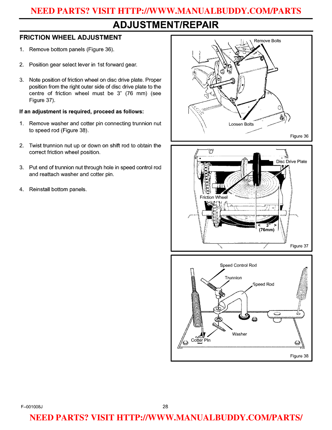
FRICTION WHEEL ADJUSTMENT
1.Remove bottom panels (Figure 36).
Remove Bolts
2.Position gear select lever in 1st forward gear.
3.Note position of friction wheel on disc drive plate. Proper position from the right outer side of disc drive plate to the centre of friction wheel must be 3" (76 mm) (see Figure 37).
If an adjustment is required, proceed as follows:
Loosen Bolts_
1.Remove washer and cotter pin connecting trunnion nut
to speed rod (Figure 38). | \ |
Figure 36
2.Twist trunnion nut up or down on shift rod to obtain the correct friction wheel position.
Disc Drive Plate
3.Put end of trunnion nut through hole in speed control rod and reattach washer and cotter pin.
4.Reinstall bottom panels.
< 3" • (76mm)
Figure 37
Speed Control Rod
Speed Rod | F_ |
r/
CotterPin
Figure 38
28 |
NEED PARTS? VISIT HTTP://WWW.MANUALBUDDY.COM/PARTS/