NEED PARTS? VISIT HTTP://WWW.MANUALBUDDY.COM/PARTS
ASSEMBLY
UPPER HANDLEAND
CRANK ASSEMBLY
1.Loosen, but do not remove the screws, flatwashers, lock- washers and hex nuts in the upper holes of the lower han- dle.
2.Raise upper handle into operating position. Upper han- dle should be to the outside of the lower handle.
NOTE: Make sure the cables are not caught between the upper and lower handle.
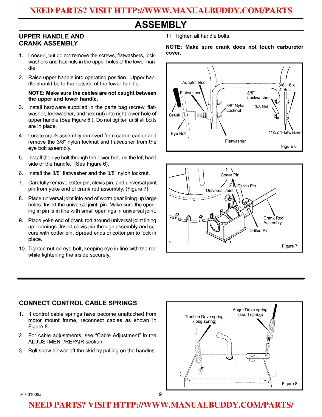
. Install hardware supplied in the parts bag (screw, flat- washer, lockwasher, and hex nut) into right lower hole of upper handle (See Figure 6 ). Do not tighten until all bolts are in place.
4.Locate crank assembly removed from carton earlier and remove the 3/8" nylon locknut and fiatwasher from the eye bolt assembly.
5.Install the eye bolt through the lower hole on the left hand side of the handle. (See Figure 6).
6.Install the 3/8" flatwasher and the 3/8" nylon locknut.
7.Carefully remove cotter pin, clevis pin, and universal joint pin from yoke end of crank rod assembly. (Figure 7)
8.Place universal joint into end of worm gear lining up large holes. Insert the universal joint pin. Make sure the open- ing in pin is in line with small openings in universal joint.
9.Place yoke end of crank rod around universal joint lining up openings. Insert clevis pin through assembly and se- cure with cotter pin. Spread ends of cotter pin to lock in place.
10.Tighten nut on eye bolt, keeping eye in line with the rod while tightening the inside securely.
11. Tighten all handle bolts.
NOTE: Make sure crank does not touch carburetor covet.
\
Adaptor
_- 2" Bolt
3/8"
Lockwasher _
3/8 Nut
\
Eye Bolt | 11/32 "Flatwasher |
| |
| Flatwasher |
| Figure 6 |
iI Cotter" Pin
LL iA Clevis Pin
Universal Joint
Crank Rod
Assembly
Drilled Pin
Figure 7
CONNECT CONTROL CABLE SPRINGS
1.If control cable springs have become unattached from motor mount frame, reconnect cables as shown in Figure 8.
2.For cable adjustments, see "Cable Adjustment" in the ADJUSTMENT/REPAIR section.
3.Roll snow blower off the skid by pulling on the handles.
Figure 8
9 |
NEED PARTS? VISIT HTTP://WWW.MANUALBUDDY.COM/PARTS/