Installation & Operation Manual
5 Hydronic piping (continued)
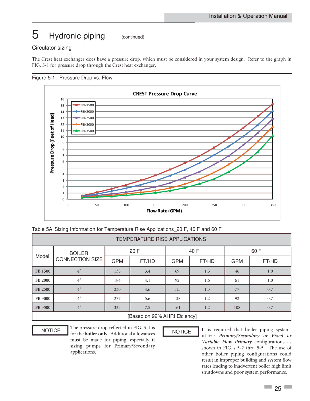
Circulator sizing
The Crest heat exchanger does have a pressure drop, which must be considered in your system design. Refer to the graph in FIG.
Figure 5-1 Pressure Drop vs. Flow
CREST Pressure Drop Curve
| 16 |
|
|
|
|
|
|
|
| 15 | FBN1500 |
|
|
|
|
|
|
Head) | 14 | FBN2000 |
|
|
|
|
|
|
13 | FBN2500 |
|
|
|
|
|
| |
12 | FBN3000 |
|
|
|
|
|
| |
of | 11 | FBN3500 |
|
|
|
|
|
|
(Feet |
|
|
|
|
|
| ||
10 |
|
|
|
|
|
|
| |
9 |
|
|
|
|
|
|
| |
Drop |
|
|
|
|
|
|
| |
8 |
|
|
|
|
|
|
| |
7 |
|
|
|
|
|
|
| |
Pressure |
|
|
|
|
|
|
| |
6 |
|
|
|
|
|
|
| |
5 |
|
|
|
|
|
|
| |
4 |
|
|
|
|
|
|
| |
|
|
|
|
|
|
|
| |
| 3 |
|
|
|
|
|
|
|
| 2 |
|
|
|
|
|
|
|
| 1 |
|
|
|
|
|
|
|
| 0 |
|
|
|
|
|
|
|
| 0 | 50 | 100 | 150 | 200 | 250 | 300 | 350 |
Flow Rate (GPM)
Table 5A Sizing Information for Temperature Rise Applications_20°F, 40°F and 60°F
TEMPERATURE RISE APPLICATIONS
Model |
| BOILER |
|
|
| 20°F |
| 40°F |
|
|
| 60°F |
| |||
|
|
|
|
|
|
|
|
|
|
|
|
| ||||
CONNECTION SIZE |
| GPM |
| FT/HD | GPM |
| FT/HD |
| GPM |
| FT/HD |
| ||||
|
|
|
|
|
|
|
|
|
| |||||||
|
|
|
|
|
|
|
|
|
|
|
|
|
|
|
| |
FB 1500 |
| 4" |
|
| 138 |
| 3.4 | 69 |
| 1.5 |
| 46 |
| 1.0 |
| |
|
|
|
|
|
|
|
|
|
|
|
|
|
|
|
| |
FB 2000 |
| 4" |
|
| 184 |
| 4.1 | 92 |
| 1.6 |
| 61 |
| 1.0 |
| |
|
|
|
|
|
|
|
|
|
|
|
|
|
|
|
| |
FB 2500 |
| 4" |
|
| 230 |
| 4.6 | 115 |
| 1.3 |
| 77 |
| 0.7 |
| |
|
|
|
|
|
|
|
|
|
|
|
|
|
|
|
| |
FB 3000 |
| 4" |
|
| 277 |
| 5.6 | 138 |
| 1.2 |
| 92 |
| 0.7 |
| |
|
|
|
|
|
|
|
|
|
|
|
|
|
|
|
| |
FB 3500 |
| 4" |
|
| 323 |
| 7.5 | 161 |
| 1.2 |
| 108 |
| 0.7 |
| |
|
|
|
|
|
|
|
|
|
|
|
|
|
|
|
| |
|
|
|
|
|
| [Based on 92% AHRI Efficiency] |
|
|
|
|
|
| ||||
|
|
|
|
|
|
|
|
|
|
| ||||||
NOTICE | The pressure drop reflected in FIG. | NOTICE | It is required that boiler piping systems | |||||||||||||
for the boiler only. Additional allowances | ||||||||||||||||
utilize | Primary/Secondary or Fixed | or | ||||||||||||||
|
| must | be made | for | piping, |
| especially if |
|
| |||||||
|
|
|
|
| Variable Flow Primary | configurations | as | |||||||||
|
| sizing | pumps | for | Primary/Secondary |
|
| |||||||||
|
|
|
| shown in FIG.’s | ||||||||||||
|
|
|
|
|
|
|
|
|
| |||||||
applications. | other boiler piping configurations could |
| |
| result in improper building and system flow |
| rates leading to inadvertent boiler high limit |
| shutdowns and poor system performance. |
![]() 25
25 ![]()