Installation & Operation Manual
2 General venting
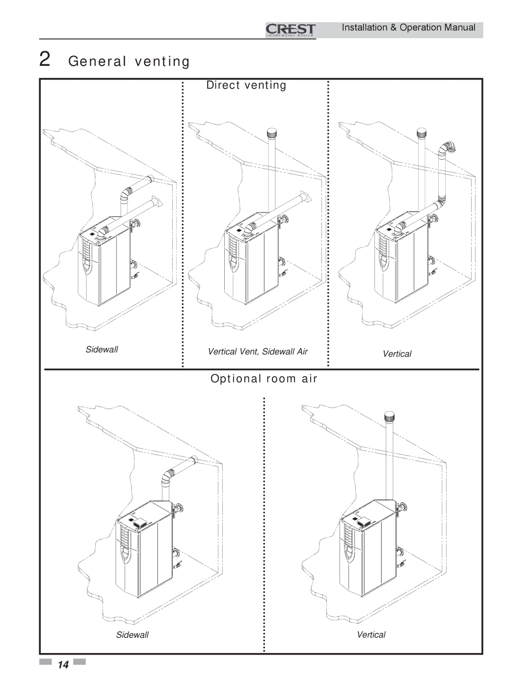
Direct venting
Sidewall | Vertical Vent, Sidewall Air | Vertical |
Optional room air
Sidewall | Vertical |
![]() 14
14 ![]()
Installation & Operation Manual
Sidewall | Vertical Vent, Sidewall Air | Vertical |
Sidewall | Vertical |
![]() 14
14 ![]()