2-2. COMPONENT LOCATIONS
CN13 |
|
贉 耟 | CN16 |
耟趪 耟 | 趭 耟 |
耟蠖 耟 |
|
| 譪 耟 |
| 譝 耟 |
潜 | 矏耟 |
|
|
|
|
|
| 莥 耟 | 莯 耟 |
| |
|
| 藿 | 袢㚬 耟 |
|
|
| |||||
潜 | 藜耟 |
|
|
|
|
|
|
|
|
|
|
潜 | 醥耟 |
|
|
|
| 鷘 |
| 莦 耟 |
|
|
|
| 莰 耟 | 莇 |
礼 耟 |
|
|
蠗 | 贇 耟 | 耟 |
豶 耟 |
| |
|
| |
|
| 媖耟 |
|
| 耟 |
|
| 襣 耟 |
|
| 耟 |
|
| |
| 耟 | 耟 |
|
| |
矏耟 |
| 藜耟 |
|
| |
| 蘠耟 | 覹 耟 |
|
| |
|
| 耟 |
2-3. HOW TO SET JUMPERS
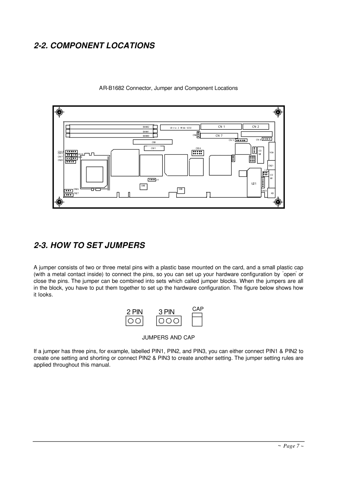
A jumper consists of two or three metal pins with a plastic base mounted on the card, and a small plastic cap (with a metal contact inside) to connect the pins, so you can set up your hardware configuration by "open" or close the pins. The jumper can be combined into sets which called jumper blocks. When the jumpers are all in the block, you have to put them together to set up the hardware configuration. The figure below shows how it looks.
2 PIN |
| 3 PIN |
| CAP | |
|
|
|
| ||
|
|
|
|
|
|
JUMPERS AND CAP
If a jumper has three pins, for example, labelled PIN1, PIN2, and PIN3, you can either connect PIN1 & PIN2 to create one setting and shorting or connect PIN2 & PIN3 to create another setting. The jumper setting rules are applied throughout this manual.
~ Page 7 ~