CY24272
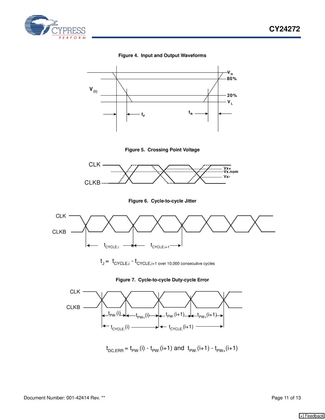
Figure 4. Input and Output Waveforms
V H |
80% |
V (t) |
20% |
V L |
tR |
tF |
Figure 5. Crossing Point Voltage
CLK
CLKB
Vx+
Vx.nom
Vx-
Figure 6. Cycle-to-cycle Jitter
CLK
CLKB
tCYCLE,i |
|
|
| tCYCLE,i+1 |
|
|
tJ = tCYCLE,i - tCYCLE,i+1 over 10,000 consecutive cycles
CLK
CLKB
Figure 7. Cycle-to-cycle Duty-cycle Error
|
|
|
|
|
|
|
|
|
|
|
|
|
|
|
|
|
|
|
|
|
| |
|
|
|
|
| tPW+(i) |
|
|
|
|
|
|
|
|
|
|
|
| tPW+(i+1) |
|
| ||
|
|
|
|
|
|
|
|
|
| |||||||||||||
|
|
|
|
|
|
|
|
|
|
|
|
|
![]() tCYCLE,(i)
tCYCLE,(i) ![]()
![]() tCYCLE,(i+1)
tCYCLE,(i+1)
tDC,ERR =
Document Number: | Page 11 of 13 |
[+] Feedback