|
|
|
|
|
|
| CY24272 | |||
|
|
|
|
|
|
|
|
|
|
|
|
|
|
|
|
|
|
|
|
| |
AC Electrical Specification |
|
|
|
|
|
|
| |||
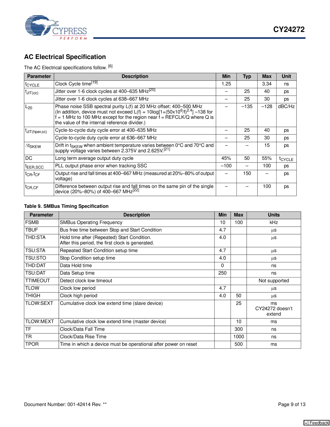
The AC Electrical specifications follow. [6] |
|
|
|
|
|
|
| |||
Parameter |
|
| Description | Min | Typ | Max |
| Unit |
|
|
t | Clock Cycle time[19] | 1.25 |
| 3.34 |
| ns |
|
| ||
CYCLE |
|
|
|
|
|
|
|
|
|
|
tJIT(cc) | Jitter over | – | 25 | 40 |
| ps |
|
| ||
| Jitter over | – | 25 | 30 |
| ps |
|
| ||
|
|
|
|
|
|
|
| |||
L20 | Phase noise SSB spectral purity L(f) at 20 MHz offset: | – |
| dBC/Hz |
|
| ||||
| (In addition, device must not exceed L(f) = 10log[1+(50x106/f)2.4] |
|
|
|
|
|
|
| ||
| f = 1 MHz to 100 MHz except for the region near f = REFCLK/Q where Q is |
|
|
|
|
|
|
| ||
| the value of the internal reference divider.) |
|
|
|
|
|
|
| ||
tJIT(hper,cc) | – | 25 | 40 |
| ps |
|
| |||
| – | 25 | 30 |
| ps |
|
| |||
|
|
|
|
|
|
|
| |||
ΔtSKEW | Drift in tSKEW when ambient temperature varies between 0°C and 70°C and | – | – | 15 |
| ps |
|
| ||
| supply voltage varies between 2.375V and 2.625V.[21] |
|
|
|
|
|
|
| ||
DC | Long term average output duty cycle | 45% | 50 | 55% |
| tCYCLE |
|
| ||
tEER,SCC | PLL output phase error when tracking SSC | – | 100 |
| ps |
|
| |||
tCR,tCF | Output rise and fall times at | – | 150 | – |
| ps |
|
| ||
| voltage) |
|
|
|
|
|
|
| ||
tCR,CF | Difference between output rise and fall times on the same pin of the single | – | – | 100 |
| ps |
|
| ||
| device |
|
|
|
|
|
|
| ||
Table 9. SMBus Timing Specification
Parameter | Description | Min | Max | Units |
FSMB | SMBus Operating Frequency | 10 | 100 | kHz |
|
|
|
|
|
TBUF | Bus free time between Stop and Start Condition | 4.7 |
| μs |
|
|
|
|
|
THD:STA | Hold time after (Repeated) Start Condition. | 4.0 |
| μs |
| After this period, the first clock is generated. |
|
|
|
TSU:STA | Repeated Start Condition setup time | 4.7 |
| μs |
|
|
|
|
|
TSU:STO | Stop Condition setup time | 4.0 |
| μs |
|
|
|
|
|
THD:DAT | Data Hold time | 0 |
| ns |
|
|
|
|
|
TSU:DAT | Data Setup time | 250 |
| ns |
|
|
|
|
|
TTIMEOUT | Detect clock low timeout |
|
| Not supported |
|
|
|
|
|
TLOW | Clock low period | 4.7 |
| μs |
|
|
|
|
|
THIGH | Clock high period | 4.0 | 50 | μs |
|
|
|
|
|
TLOW:SEXT | Cumulative clock low extend time (slave device) |
| 25 | ms |
|
|
|
| CY24272 doesn’t |
|
|
|
| extend |
TLOW:MEXT | Cumulative clock low extend time (master device) |
| 10 | ms |
|
|
|
|
|
TF | Clock/Data Fall Time |
| 300 | ns |
|
|
|
|
|
TR | Clock/Data Rise Time |
| 1000 | ns |
|
|
|
|
|
TPOR | Time in which a device must be operational after power on reset |
| 500 | ms |
|
|
|
|
|
Document Number: | Page 9 of 13 |
[+] Feedback
