CY62147DV30
Pin Configuration[2, 3, 4]
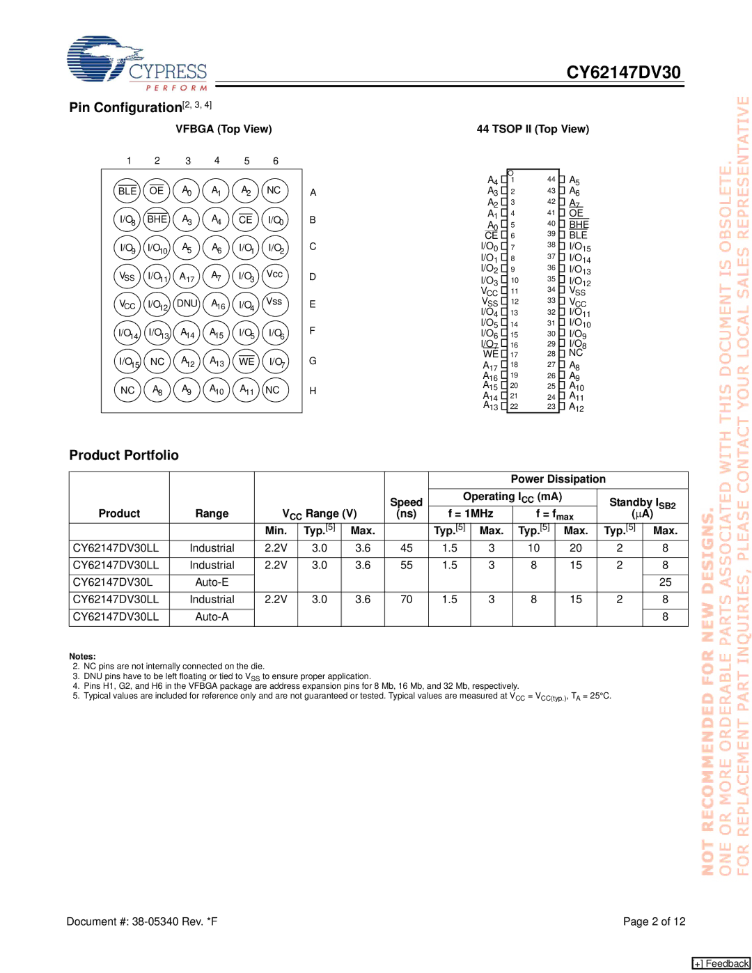
VFBGA (Top View) | 44 TSOP II (Top View) |
1 | 2 | 3 | 4 | 5 | 6 |
|
BLE | OE | A0 | A1 | A2 | NC | A |
I/O8 | BHE | A3 | A4 | CE | I/O0 | B |
I/O9 | I/O10 | A5 | A6 | I/O1 | I/O2 | C |
VSS | I/O11 | A17 | A7 | I/O3 | Vcc | D |
VCC | I/O | DNU | A16 | I/O | Vss | E |
| 12 |
|
| 4 |
|
|
I/O14 | I/O13 | A14 | A15 | I/O5 | I/O6 | F |
I/O | NC | A | A13 | WE | I/O | G |
15 |
| 12 |
|
| 7 |
|
NC | A8 | A9 | A10 | A11 | NC | H |
A4 ![]() A3
A3 ![]() A2
A2 ![]() A1
A1 ![]()
A0 ![]()
CE ![]() I/O0
I/O0 ![]() I/O1
I/O1 ![]() I/O2
I/O2 ![]() I/O3
I/O3 ![]()
VCC ![]() VSS
VSS ![]() I/O4
I/O4 ![]() I/O5
I/O5 ![]() I/O6
I/O6 ![]() I/O7
I/O7 ![]()
WE ![]()
A17 ![]()
A16
A15 ![]()
A14
A13 ![]()
1
2
3
4
5
6
7
8
9
10
11
12
13
14
15
16
17
18
19
20
21
22
44 ![]() A5
A5
43 ![]() A6
A6
42 ![]() A7
A7
41 ![]() OE
OE
40 ![]() BHE
BHE
39 ![]() BLE
BLE
38 ![]() I/O15
I/O15
37 ![]() I/O14
I/O14
36 ![]() I/O13
I/O13
35 ![]() I/O12
I/O12
34 ![]() VSS
VSS
33 ![]() VCC
VCC
32 ![]() I/O11
I/O11
31 ![]() I/O10
I/O10
30 ![]() I/O9
I/O9
29 ![]() I/O8
I/O8
28 ![]() NC
NC
27 ![]() A8
A8
26 ![]() A9
A9
25 ![]() A10
A10
24 ![]() A11
A11
23 ![]() A12
A12
Product Portfolio
|
|
|
|
|
|
|
|
|
| Power Dissipation |
| |||
|
|
|
|
|
|
| Speed | Operating ICC (mA) | Standby ISB2 | |||||
Product | Range | V | CC | Range (V) | (ns) | f = 1MHz |
| f = f | max | (∝A) | ||||
|
|
|
|
|
|
|
|
|
|
|
| |||
|
| Min. |
|
| Typ.[5] | Max. |
| Typ.[5] | Max. | Typ.[5] | Max. | Typ.[5] | Max. | |
CY62147DV30LL | Industrial | 2.2V |
|
| 3.0 | 3.6 | 45 | 1.5 | 3 |
| 10 | 20 | 2 | 8 |
|
|
|
|
|
|
|
|
|
|
|
|
|
|
|
CY62147DV30LL | Industrial | 2.2V |
|
| 3.0 | 3.6 | 55 | 1.5 | 3 |
| 8 | 15 | 2 | 8 |
|
|
|
|
|
|
|
|
|
|
|
|
|
|
|
CY62147DV30L |
|
|
|
|
|
|
|
|
|
|
|
| 25 | |
|
|
|
|
|
|
|
|
|
|
|
|
|
|
|
CY62147DV30LL | Industrial | 2.2V |
|
| 3.0 | 3.6 | 70 | 1.5 | 3 |
| 8 | 15 | 2 | 8 |
|
|
|
|
|
|
|
|
|
|
|
|
|
|
|
CY62147DV30LL |
|
|
|
|
|
|
|
|
|
|
|
|
| 8 |
|
|
|
|
|
|
|
|
|
|
|
|
|
|
|
Notes:
2.NC pins are not internally connected on the die.
3.DNU pins have to be left floating or tied to VSS to ensure proper application.
4.Pins H1, G2, and H6 in the VFBGA package are address expansion pins for 8 Mb, 16 Mb, and 32 Mb, respectively.
5.Typical values are included for reference only and are not guaranteed or tested. Typical values are measured at VCC = VCC(typ.), TA = 25°C.
Document #: | Page 2 of 12 |
[+] Feedback
