CY7C1318CV18
CY7C1320CV18
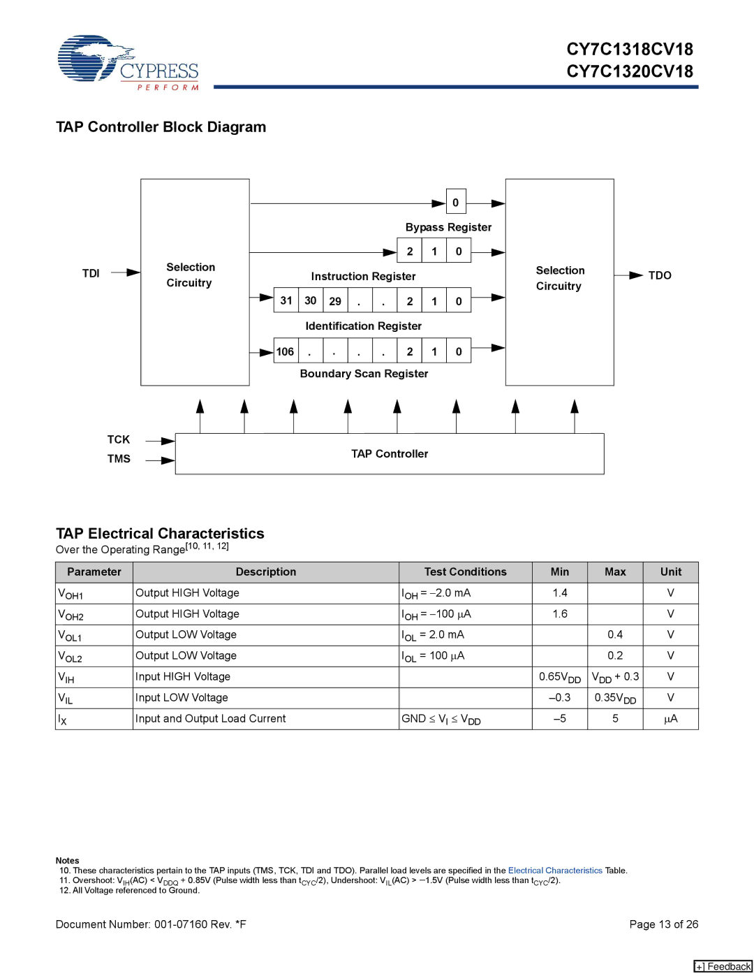
TAP Controller Block Diagram
|
|
|
|
|
|
|
|
|
|
|
|
|
|
|
|
|
|
|
|
|
|
|
|
|
|
|
|
|
|
|
|
|
|
|
|
|
|
|
|
|
|
|
|
|
|
|
|
|
|
|
| 0 |
|
|
|
|
|
| |
|
|
|
|
|
|
|
|
|
|
|
|
|
|
|
|
|
|
|
|
|
|
|
|
|
|
|
| ||
|
|
|
|
|
|
|
|
|
|
|
|
|
|
|
|
|
|
|
|
|
|
|
|
|
|
|
|
|
|
|
|
|
|
|
|
|
|
|
|
|
|
|
|
|
|
|
|
| Bypass Register |
|
|
| |||||||
|
|
|
|
|
|
|
|
|
|
|
|
|
|
|
|
|
|
|
|
|
|
|
|
|
|
|
|
|
|
TDI |
|
|
|
|
| Selection |
|
|
|
|
|
|
|
|
| 2 | 1 | 0 |
|
|
|
| Selection | ||||||
|
|
|
|
|
|
|
|
|
|
|
|
|
|
|
|
|
| ||||||||||||
|
|
|
|
|
|
|
|
|
|
|
|
|
|
|
|
|
|
|
|
|
|
| |||||||
|
|
|
|
|
|
| Instruction Register |
|
|
|
|
|
|
|
| ||||||||||||||
|
|
|
|
| Circuitry |
|
|
|
|
|
|
|
|
|
|
|
| ||||||||||||
|
|
|
|
|
|
|
|
|
|
|
|
|
|
|
|
|
|
|
|
|
|
|
| Circuitry | |||||
|
|
|
|
|
| 31 |
| 30 | 29 | . | . | 2 | 1 | 0 |
|
|
| ||||||||||||
|
|
|
|
|
|
|
|
|
|
|
|
|
|
|
|
|
|
| |||||||||||
|
|
|
|
|
|
|
|
|
|
|
|
|
|
|
|
|
| ||||||||||||
|
|
|
|
|
|
|
|
|
|
|
|
|
|
|
|
|
|
|
|
|
|
|
|
|
|
|
|
|
|
|
|
|
|
|
|
|
|
|
|
|
|
|
| Identification Register |
|
|
|
|
|
|
|
| |||||||
|
|
|
|
|
|
|
|
|
|
|
|
|
|
|
|
|
|
|
|
|
|
|
|
|
|
|
|
| |
|
|
|
|
|
|
|
|
|
|
|
| 106 | . | . | . | . | 2 | 1 | 0 |
|
|
|
|
|
| ||||
|
|
|
|
|
|
|
|
|
|
|
|
|
|
|
|
|
| ||||||||||||
|
|
|
|
|
|
|
|
|
|
|
|
|
|
|
|
|
| ||||||||||||
|
|
|
|
|
|
|
|
|
|
|
|
|
|
|
|
|
|
|
|
|
|
|
|
|
|
|
|
|
|
|
|
|
|
|
|
|
|
|
|
|
|
|
| Boundary Scan Register |
|
|
|
|
|
|
|
| |||||||
|
|
|
|
|
|
|
|
|
|
|
|
|
|
|
|
|
|
|
|
|
|
|
|
|
|
|
|
|
|
| TCK |
|
|
|
|
|
|
|
|
|
|
|
|
|
|
|
|
|
|
|
|
|
|
|
| ||||
|
|
|
|
|
|
|
|
|
|
|
|
|
|
|
|
|
|
|
|
|
|
|
|
|
| ||||
|
|
|
|
|
|
|
|
| TAP Controller |
|
|
|
|
|
|
|
| ||||||||||||
|
|
|
|
|
|
|
|
|
|
|
|
|
|
|
|
|
|
| |||||||||||
| TMS |
|
|
|
|
|
|
|
|
|
|
|
|
|
|
|
|
|
|
| |||||||||
|
|
|
|
|
|
|
|
|
|
|
|
|
|
|
|
|
|
|
|
|
|
|
|
|
| ||||
|
|
|
|
|
|
|
|
|
|
|
|
|
|
|
|
|
|
|
|
|
|
|
|
|
|
|
|
|
|
![]()
![]() TDO
TDO
TAP Electrical Characteristics
Over the Operating Range[10, 11, 12]
Parameter | Description | Test Conditions | Min | Max | Unit |
VOH1 | Output HIGH Voltage | IOH = −2.0 mA | 1.4 |
| V |
VOH2 | Output HIGH Voltage | IOH = −100 μA | 1.6 |
| V |
VOL1 | Output LOW Voltage | IOL = 2.0 mA |
| 0.4 | V |
VOL2 | Output LOW Voltage | IOL = 100 μA |
| 0.2 | V |
VIH | Input HIGH Voltage |
| 0.65VDD | VDD + 0.3 | V |
VIL | Input LOW Voltage |
| 0.35VDD | V | |
IX | Input and Output Load Current | GND ≤ VI ≤ VDD | 5 | μA |
Notes
10.These characteristics pertain to the TAP inputs (TMS, TCK, TDI and TDO). Parallel load levels are specified in the Electrical Characteristics Table.
11.Overshoot: VIH(AC) < VDDQ + 0.85V (Pulse width less than tCYC/2), Undershoot: VIL(AC) > −1.5V (Pulse width less than tCYC/2).
12.All Voltage referenced to Ground.
Document Number: | Page 13 of 26 |
[+] Feedback