CY7C1330AV25
PRELIMINARYCY7C1332AV25
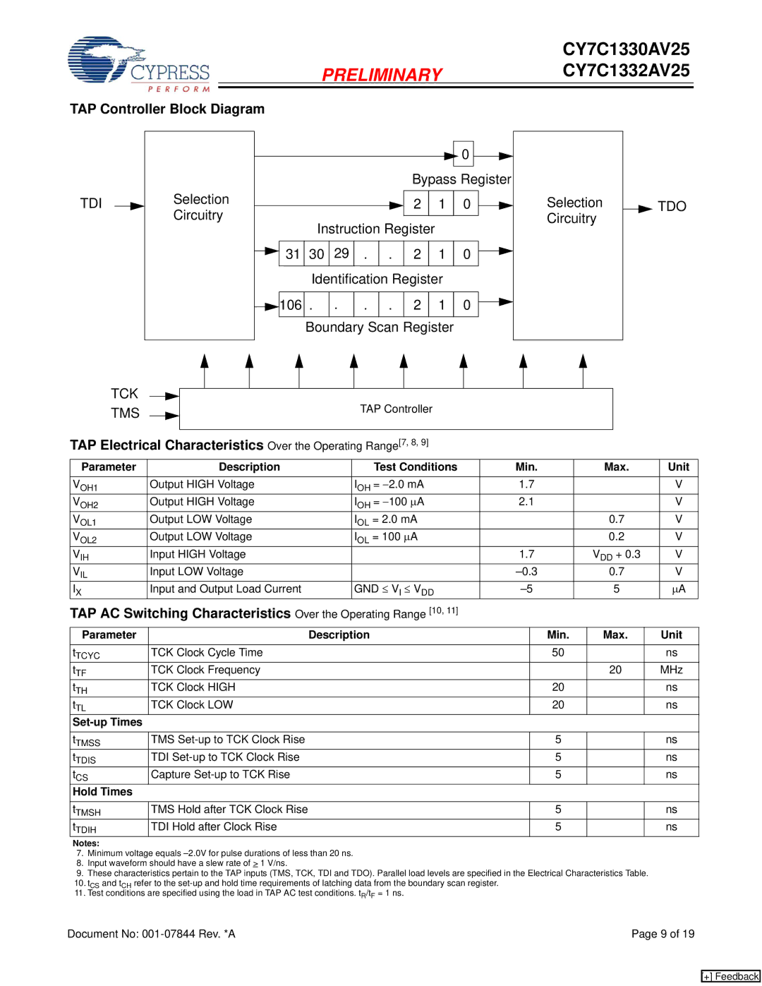
TAP Controller Block Diagram
TDI
|
|
|
|
|
| 0 |
|
|
|
|
|
| Bypass Register |
|
| ||
Selection |
|
|
| 2 | 1 | 0 | Selection | TDO |
Circuitry | Instruction Register |
|
| Circuitry |
| |||
|
|
|
|
| ||||
31 | 30 29 . | . | 2 | 1 | 0 |
|
| |
| Identification Register |
|
|
| ||||
106 | . . | . | . | 2 | 1 | 0 |
|
|
| Boundary Scan Register |
|
|
| ||||
TCK TMS
TAP Controller
TAP Electrical Characteristics Over the Operating Range[7, 8, 9]
Parameter | Description | Test Conditions | Min. | Max. | Unit |
VOH1 | Output HIGH Voltage | IOH = −2.0 mA | 1.7 |
| V |
VOH2 | Output HIGH Voltage | IOH = −100 ∝A | 2.1 |
| V |
VOL1 | Output LOW Voltage | IOL = 2.0 mA |
| 0.7 | V |
VOL2 | Output LOW Voltage | IOL = 100 ∝A |
| 0.2 | V |
VIH | Input HIGH Voltage |
| 1.7 | VDD + 0.3 | V |
VIL | Input LOW Voltage |
| 0.7 | V | |
IX | Input and Output Load Current | GND ≤ VI ≤ VDD | 5 | ∝A | |
TAP AC Switching Characteristics Over the Operating Range [10, 11] |
|
|
| ||
Parameter | Description | Min. | Max. | Unit |
tTCYC | TCK Clock Cycle Time | 50 |
| ns |
tTF | TCK Clock Frequency |
| 20 | MHz |
tTH | TCK Clock HIGH | 20 |
| ns |
tTL | TCK Clock LOW | 20 |
| ns |
|
|
|
|
|
|
|
|
|
|
tTMSS | TMS | 5 |
| ns |
tTDIS | TDI | 5 |
| ns |
tCS | Capture | 5 |
| ns |
Hold Times |
|
|
|
|
tTMSH | TMS Hold after TCK Clock Rise | 5 |
| ns |
tTDIH | TDI Hold after Clock Rise | 5 |
| ns |
Notes:
7.Minimum voltage equals
8.Input waveform should have a slew rate of > 1 V/ns.
9.These characteristics pertain to the TAP inputs (TMS, TCK, TDI and TDO). Parallel load levels are specified in the Electrical Characteristics Table.
10. tCS and tCH refer to the
Document No: | Page 9 of 19 |
[+] Feedback