CY7C1511JV18, CY7C1526JV18
CY7C1513JV18, CY7C1515JV18
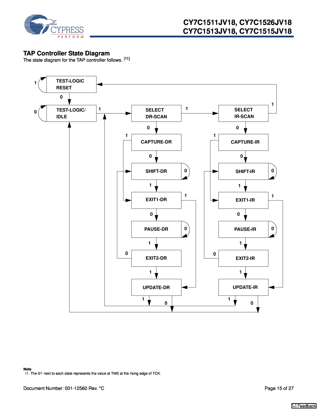
TAP Controller State Diagram
The state diagram for the TAP controller follows. [11]
1![]()
0![]()
0
1 |
| 1 | 1 |
SELECT | SELECT | ||
|
| ||
| 0 |
| 0 |
| 1 |
| 1 |
|
| ||
0 |
| 0 |
|
0 | 0 | ||
1 |
| 1 |
|
1 | 1 | ||
|
| ||
0 |
| 0 |
|
0 | 0 | ||
1 |
| 1 |
|
0 |
| 0 |
|
|
| ||
1 |
| 1 |
|
|
| ||
1 |
| 1 |
|
0 |
| 0 |
|
Note
11. The 0/1 next to each state represents the value at TMS at the rising edge of TCK.
Document Number: | Page 15 of 27 |
[+] Feedback