CY7C1510KV18, CY7C1525KV18


CY7C1512KV18, CY7C1514KV18


Pin Definitions (continued)


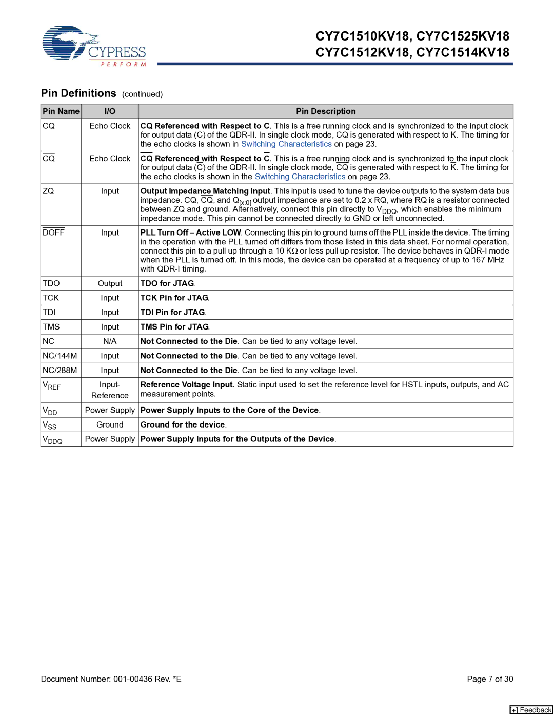
Pin Name

I/O


Pin Description


CQ

Echo Clock


CQ Referenced with Respect to C. This is a free running clock and is synchronized to the input clock


for output data (C) of the QDR-II. In single clock mode, CQ is generated with respect to K. The timing for


the echo clocks is shown in Switching Characteristics on page 23.


Echo Clock


Referenced with Respect to


. This is a free running clock and is synchronized to the input clock


CQ


CQ

C


for output data

(C)

of the QDR-II. In single clock mode, CQ is generated with respect to K. The timing for


the echo clocks is shown in the Switching Characteristics on page 23.


ZQ

Input


Output Impedance Matching Input. This input is used to tune the device outputs to the system data bus


impedance. CQ, CQ, and Q[x:0] output impedance are set to 0.2 x RQ, where RQ is a resistor connected


between ZQ and ground. Alternatively, connect this pin directly to VDDQ, which enables the minimum


impedance mode. This pin cannot be connected directly to GND or left unconnected.


Input


PLL Turn Off Active LOW. Connecting this pin to ground turns off the PLL inside the device. The timing


DOFF


in the operation with the PLL turned off differs from those listed in this data sheet. For normal operation,


connect this pin to a pull up through a 10 KΩ or less pull up resistor. The device behaves in QDR-I mode


when the PLL is turned off. In this mode, the device can be operated at a frequency of up to 167 MHz


with QDR-I timing.


TDO

Output


TDO for JTAG.


TCK

Input


TCK Pin for JTAG.


TDI

Input


TDI Pin for JTAG.


TMS

Input


TMS Pin for JTAG.


NC

N/A


Not Connected to the Die. Can be tied to any voltage level.


NC/144M

Input


Not Connected to the Die. Can be tied to any voltage level.


NC/288M

Input


Not Connected to the Die. Can be tied to any voltage level.


VREF

Input-


Reference Voltage Input. Static input used to set the reference level for HSTL inputs, outputs, and AC


Reference


measurement points.


VDD

Power Supply


Power Supply Inputs to the Core of the Device.


VSS

Ground


Ground for the device.


VDDQ

Power Supply


Power Supply Inputs for the Outputs of the Device.

Document Number: 001-00436 Rev. *E

Page 7 of 30

[+] Feedback

Page 7
Image 7
Cypress CY7C1525KV18 manual Referenced with Respect to, TDO for Jtag, TCK Pin for Jtag, TDI Pin for Jtag, TMS Pin for Jtag

CY7C1510KV18, CY7C1514KV18, CY7C1512KV18, CY7C1525KV18 specifications

Cypress Semiconductor, a leading player in the memory solutions market, has developed a range of high-performance memory components, notably the CY7C1525KV18, CY7C1512KV18, CY7C1514KV18, and CY7C1510KV18. These devices are part of the company's advanced SRAM family and are noteworthy for their speed, efficiency, and flexibility in various applications.

The CY7C1525KV18 is a 2Mb asynchronous SRAM that boasts low latency and high-speed performance, making it ideal for applications that require fast data access and processing. It features a 1.8V operation, which significantly contributes to its power efficiency, an essential factor in today's energy-conscious designs. The architecture of the CY7C1525KV18 employs a dual-port configuration, enabling simultaneous read and write operations, which enhances the system performance in multi-threaded environments.

Similar in design but tailored for different capacities, the CY7C1512KV18 and CY7C1514KV18 deliver 1.5Mb and 1Mb memory density, respectively. Both chips are built with advanced CMOS technology, ensuring low power consumption and high-speed access times that reach up to 66 MHz. Such speed allows them to support high-performance applications, including networking equipment, telecom systems, and automotive electronics.

The CY7C1510KV18, meanwhile, offers a lower memory capacity at 512Kb but retains the key performance traits of its higher-capacity counterparts. It is particularly well-suited for applications where space is at a premium yet where high-speed data processing is still crucial.

All four SRAM devices are characterized by their fast access times, which can be as low as 10 ns, making them highly effective in environments that require real-time data handling. Moreover, their low standby and active power consumption aligns with the growing demand for energy-efficient solutions in modern electronics.

Additionally, these products come with a variety of packaging options to fit diverse application requirements, enhancing their versatility across industrial, automotive, and consumer electronics sectors. The combination of speed, efficiency, and flexible configurations renders the Cypress CY7C1525KV18, CY7C1512KV18, CY7C1514KV18, and CY7C1510KV18 an excellent choice for engineers seeking reliable high-performance memory solutions.