PRELIMINARY

CY14B102L, CY14B102N

Pinouts (continued)

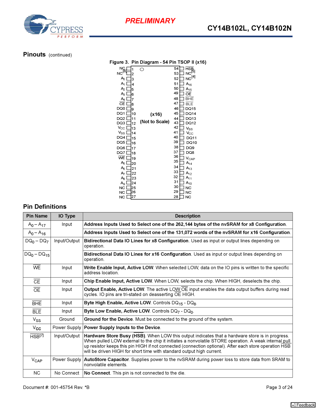
Figure 3. Pin Diagram - 54 Pin TSOP II (x16)


NC


1


NC[6]


2


A0


3


A1


4


A2


5


A3


6


A4


7


CE


8


DQ0


9


DQ1


10

DQ2


11


DQ3


12


VCC


13


VSS


14


DQ4


15


DQ5


16


DQ6


17

DQ7


18


WE


19


A5


20


A6


21


A7


22


A8


23


A9


24


NC


25


NC


26


NC


27


(x16) (Not to Scale)

54HSB

53 NC[5]

52 NC[4]

51 A16

50 A15

49 OE

48 BHE

47 BLE

46 DQ15

45 DQ14

44 DQ13

43 DQ12

42 VSS

41 VCC

40 DQ11

39 DQ10

38 DQ9

37 DQ8

36 VCAP

35 A14

34 A13

33 A12

32 A11

31 A10

30 NC

29 NC

28 NC

Pin Definitions

Pin Name

IO Type


Description


A0 – A17

Input

Address Inputs Used to Select one of the 262,144 bytes of the nvSRAM for x8 Configuration.

A0 – A16


Address Inputs Used to Select one of the 131,072 words of the nvSRAM for x16 Configuration.

DQ0 – DQ7

Input/Output

Bidirectional Data IO Lines for x8 Configuration. Used as input or output lines depending on


operation.


DQ0 – DQ15


Bidirectional Data IO Lines for x16 Configuration. Used as input or output lines depending on


operation.


Input

Write Enable Input, Active LOW. When selected LOW, data on the IO pins is written to the specific


WE


address location.


Input

Chip Enable Input, Active LOW. When LOW, selects the chip. When HIGH, deselects the chip.


CE


Input

Output Enable, Active LOW. The active LOW


input enables the data output buffers during read


OE


OE


cycles. IO pins are tri-stated on deasserting OE HIGH.


Input

Byte High Enable, Active LOW. Controls DQ15 - DQ8.


BHE


Input

Byte Low Enable, Active LOW. Controls DQ7 - DQ0.


BLE


VSS

Ground

Ground for the Device. Must be connected to the ground of the system.


VCC

Power Supply

Power Supply Inputs to the Device.


[7]

Input/Output

Hardware Store Busy

(HSB)

. When LOW this output indicates that a hardware store is in progress.


HSB


When pulled LOW external to the chip it initiates a nonvolatile STORE operation. A weak internal pull


up resistor keeps this pin HIGH if not connected (connection optional). After each store operation HSB


will be driven HIGH for short time with standard output high current.


VCAP

Power Supply

AutoStore Capacitor. Supplies power to the nvSRAM during power loss to store data from SRAM to


nonvolatile elements.


NC

No Connect

No Connect. This pin is not connected to the die.


Document #: 001-45754 Rev. *B

Page 3 of 24

[+] Feedback

Page 3
Image 3
Cypress CY14B102L, nvSRAM manual Pin Definitions

CY14B102L, nvSRAM specifications

Cypress nvSRAM CY14B102L is a sophisticated memory solution designed to bridge the gap between volatile and non-volatile memory technologies. This device offers a unique blend of SRAM speed with the non-volatility of Flash memory, making it an ideal choice for applications that require data retention without the need for continuous power.

One of the standout features of the CY14B102L is its ability to retain data for over 20 years without power, thanks to its innovative non-volatile SRAM technology. This means that critical information can be stored safely during power outages or system failures, ensuring data integrity in mission-critical applications. The device uses a reliable, self-timed write process, which simplifies the write operation and enhances system efficiency by eliminating the need for complex write management processes.

With a capacity of 1 megabit (128 K x 8), the CY14B102L offers ample storage for a wide variety of applications. Its fast access times, typically around 45 ns, make it suitable for high-speed operations typically associated with SRAMs. This rapid access is paramount for real-time applications where delays can lead to critical failures or data corruption.

The CY14B102L utilizes a CMOS process technology that not only contributes to its low power consumption but also ensures high reliability and durability. Operating in the wide temperature range of -40°C to +125°C, this nvSRAM is well-suited for automotive, industrial, and telecommunications applications.

In terms of connectivity, the CY14B102L supports a standard SRAM interface, simplifying integration into existing systems. Additionally, its ease of use is further enhanced by being available in a variety of package options, allowing designers to select the best fit for their needs without compromising on performance.

In conclusion, the Cypress nvSRAM CY14B102L is a powerful memory device that combines the speed of SRAM with non-volatile storage capabilities. With its extended data retention, fast access times, efficient write processes, and robust design, it is an excellent choice for applications that demand both speed and reliability, making it an invaluable asset for engineers looking to optimize system performance while maintaining data integrity.