FREESTANDING INSTALLATION . . . CON’T
These styles of installation are highly recommended, due to possible backpressure in the exhaust caused by airflow around the outside of the structure, snow
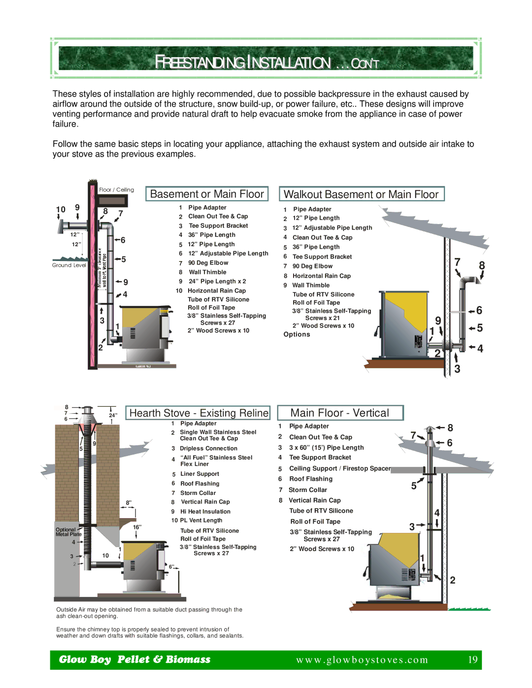
Follow the same basic steps in locating your appliance, attaching the exhaust system and outside air intake to your stove as the previous examples.
Floor / Ceiling Basement or Main Floor
Walkout Basement or Main Floor
10 9
12” |
12” |
Ground Level
8 | 7 |
| 6 |
| 5 |
| 9 |
| 4 |
3 | 1 |
| |
2 |
|
1Pipe Adapter
2Clean Out Tee & Cap
3Tee Support Bracket
436” Pipe Length
512” Pipe Length
612” Adjustable Pipe Length
790 Deg Elbow
8Wall Thimble
924” Pipe Length x 2
10Horizontal Rain Cap Tube of RTV Silicone Roll of Foil Tape
3/8” Stainless
2” Wood Screws x 10
1Pipe Adapter
212” Pipe Length
312” Adjustable Pipe Length
4Clean Out Tee & Cap
536” Pipe Length
6Tee Support Bracket
790 Deg Elbow
8Horizontal Rain Cap
9 Wall Thimble
Tube of RTV Silicone
Roll of Foil Tape
3/8” Stainless
Screws x 21
2” Wood Screws x 10
Options
7 | 8 | |
9 | 6 | |
5 | ||
1 |
2 | 4 |
| |
| 3 |
8 |
| Hearth Stove - Existing Reline | ||
7 | 24” | |||
6 |
|
| 1 | Pipe Adapter |
|
|
| ||
|
|
| 2 | Single Wall Stainless Steel |
| 9 |
|
| Clean Out Tee & Cap |
5 |
| 3 | Dripless Connection | |
|
| |||
|
|
| 4 | “All Fuel” Stainless Steel |
|
|
|
| Flex Liner |
|
|
| 5 | Liner Support |
|
|
| 6 | Roof Flashing |
|
|
| 7 | Storm Collar |
|
| 8” | 8 | Vertical Rain Cap |
|
|
| 9 | Hi Heat Insulation |
|
|
| 10 PL Vent Length | |
Optional |
|
| 16” | Tube of RTV Silicone |
|
|
| ||
Metal Plate |
|
|
| Roll of Foil Tape |
4 |
|
|
| |
| 1 |
| 3/8” Stainless | |
|
|
| ||
3 | 10 |
| Screws x 27 | |
|
| |||
|
|
| ||
2 |
|
| 6” |
|
|
|
|
| |
Outside Air may be obtained from a suitable duct passing through the ash
Ensure the chimney top is properly sealed to prevent intrusion of weather and down drafts with suitable flashings, collars, and sealants.
| Main Floor - Vertical |
|
|
1 | Pipe Adapter | 7 | 8 |
2 | Clean Out Tee & Cap | 6 | |
3 | 3 x 60” (15’) Pipe Length |
| |
4 | Tee Support Bracket |
|
|
5 | Ceiling Support / Firestop Spacer |
|
|
6 | Roof Flashing | 5 |
|
7 | Storm Collar |
| |
8 | Vertical Rain Cap |
|
|
| Tube of RTV Silicone |
| 4 |
| Roll of Foil Tape |
| |
| 3 |
| |
| 3/8” Stainless |
| |
| Screws x 27 |
|
|
| 2” Wood Screws x 10 |
| 1 |
|
|
| |
|
|
| 2 |
Glow Boy Pellet & Biomass | www.glowboystoves.com | 19 |
|
| 19 |
|
|
|