|
| FREESTANDING INSTALLATION . . . CON’T |
|
| |||
11 |
|
|
|
|
|
|
|
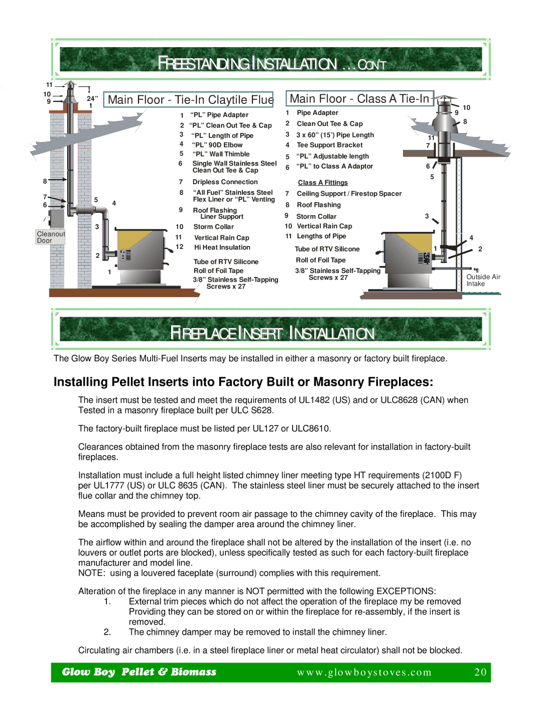
10 | 24” | Main Floor - |
| Main Floor - Class A |
|
| |
9 |
|
| 10 | ||||
|
| 1 | “PL” Pipe Adapter | 1 | Pipe Adapter | 9 | |
|
| 2 | “PL” Clean Out Tee & Cap | 2 | Clean Out Tee & Cap |
| 8 |
| 3 | “PL” Length of Pipe | 3 | 3 x 60” (15’) Pipe Length | 11 |
| 4 | “PL” 90D Elbow | 4 | Tee Support Bracket | 7 |
| 5 | “PL” Wall Thimble | 5 | “PL” Adjustable length |
|
| 6 | Single Wall Stainless Steel |
| ||
| 6 | “PL” to Class A Adaptor | 6 | ||
|
| Clean Out Tee & Cap | |||
|
|
|
| 5 | |
8 | 7 | Dripless Connection |
| Class A Fittings | |
|
|
7 | 5 | 8 | “All Fuel” Stainless Steel | 7 | Ceiling Support / Firestop Spacer |
|
|
4 | Flex Liner or “PL” Venting | 8 | Roof Flashing |
|
| ||
6 |
| Roof Flashing |
|
| |||
|
| 9 | 9 | Storm Collar | 3 |
| |
|
|
| Liner Support |
| |||
Cleanout | 3 | 10 | Storm Collar | 10 | Vertical Rain Cap |
|
|
| 11 | Vertical Rain Cap | 11 | Lengths of Pipe |
| 4 | |
Door |
|
| |||||
| 12 | Hi Heat Insulation |
| Tube of RTV Silicone | 1 | 2 | |
| 2 |
| |||||
|
| Tube of RTV Silicone |
| Roll of Foil Tape |
|
| |
|
|
|
|
|
|
1 | Roll of Foil Tape | 3/8” Stainless | Outside Air |
| 3/8” Stainless | Screws x 27 | |
| Screws x 27 |
| Intake |
|
|
|
FIREPLACE INSERT INSTALLATION
The Glow Boy Series
Installing Pellet Inserts into Factory Built or Masonry Fireplaces:
The insert must be tested and meet the requirements of UL1482 (US) and or ULC8628 (CAN) when Tested in a masonry fireplace built per ULC S628.
The
Clearances obtained from the masonry fireplace tests are also relevant for installation in
Installation must include a full height listed chimney liner meeting type HT requirements (2100D F) per UL1777 (US) or ULC 8635 (CAN). The stainless steel liner must be securely attached to the insert flue collar and the chimney top.
Means must be provided to prevent room air passage to the chimney cavity of the fireplace. This may be accomplished by sealing the damper area around the chimney liner.
The airflow within and around the fireplace shall not be altered by the installation of the insert (i.e. no louvers or outlet ports are blocked), unless specifically tested as such for each
NOTE: using a louvered faceplate (surround) complies with this requirement.
Alteration of the fireplace in any manner is NOT permitted with the following EXCEPTIONS:
1.External trim pieces which do not affect the operation of the fireplace my be removed Providing they can be stored on or within the fireplace for
2.The chimney damper may be removed to install the chimney liner.
Circulating air chambers (i.e. in a steel fireplace liner or metal heat circulator) shall not be blocked.
Glow Boy Pellet & Biomass | www.glowboystoves.com | 20 |
|
| 20 |
|
|
|