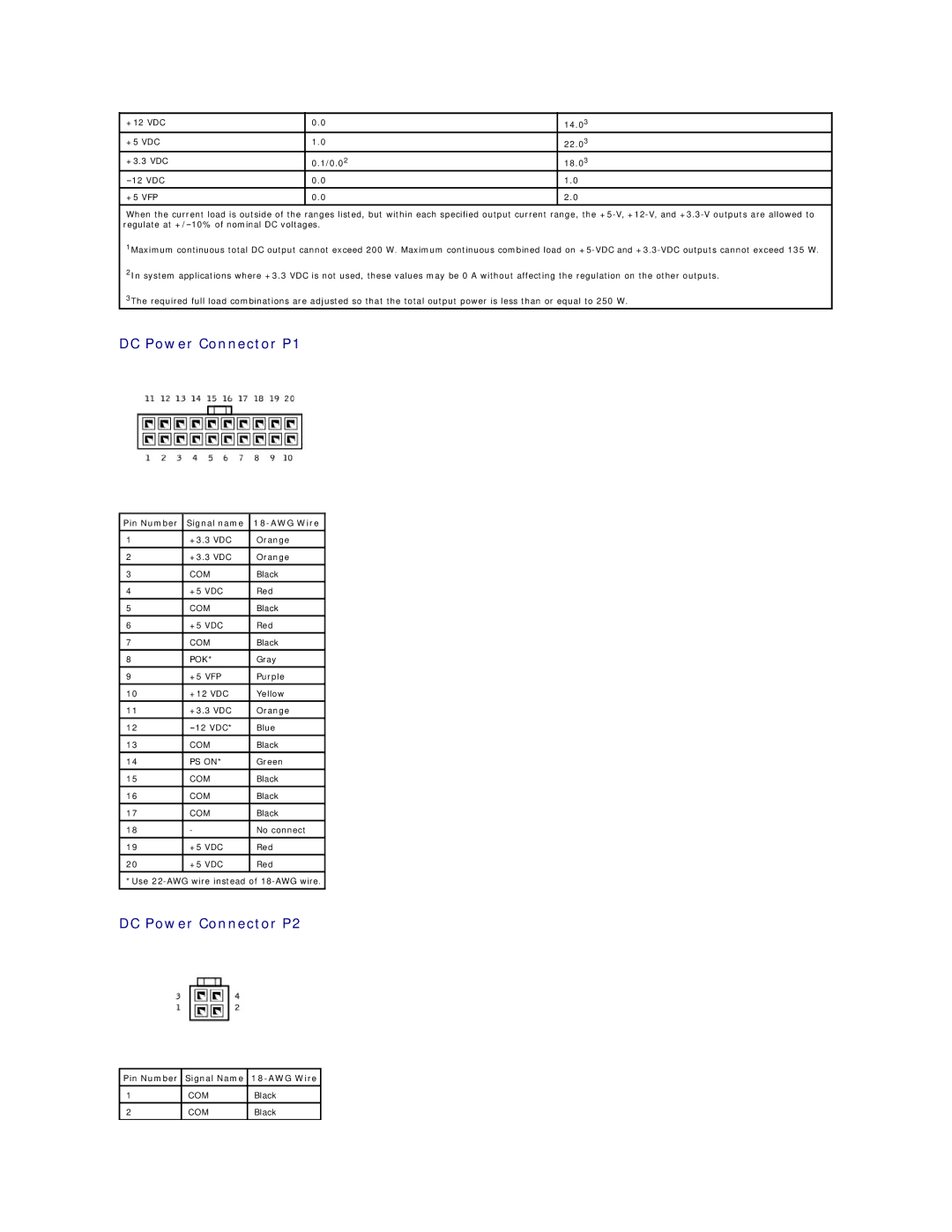
+12 VDC | 0.0 | 14.03 |
+5 VDC | 1.0 | 22.03 |
+3.3 VDC | 0.1/0.02 | 18.03 |
0.0 | 1.0 | |
|
|
|
+5 VFP | 0.0 | 2.0 |
|
|
|
When the current load is outside of the ranges listed, but within each specified output current range, the
1Maximum continuous total DC output cannot exceed 200 W. Maximum continuous combined load on
2In system applications where +3.3 VDC is not used, these values may be 0 A without affecting the regulation on the other outputs.
3The required full load combinations are adjusted so that the total output power is less than or equal to 250 W.
DC Power Connector P1
Pin Number | Signal name |
|
|
|
|
1 | +3.3 VDC | Orange |
|
|
|
2 | +3.3 VDC | Orange |
|
|
|
3 | COM | Black |
|
|
|
4 | +5 VDC | Red |
|
|
|
5 | COM | Black |
|
|
|
6 | +5 VDC | Red |
|
|
|
7 | COM | Black |
8 | POK* | Gray |
|
|
|
9 | +5 VFP | Purple |
|
|
|
10 | +12 VDC | Yellow |
|
|
|
11 | +3.3 VDC | Orange |
|
|
|
12 | Blue | |
|
|
|
13 | COM | Black |
|
|
|
14 | PS ON* | Green |
|
|
|
15 | COM | Black |
16 | COM | Black |
|
|
|
17 | COM | Black |
|
|
|
18 | - | No connect |
|
|
|
19 | +5 VDC | Red |
|
|
|
20 | +5 VDC | Red |
|
|
|
*Use
DC Power Connector P2
Pin Number Signal Name 18-AWG Wire
1 | COM | Black |
2 | COM | Black |
