CHAPTER 4: INSTALLING AND REPLACING COMPONENTS
5
4
3
|
| 1 |
|
|
|
| 2 |
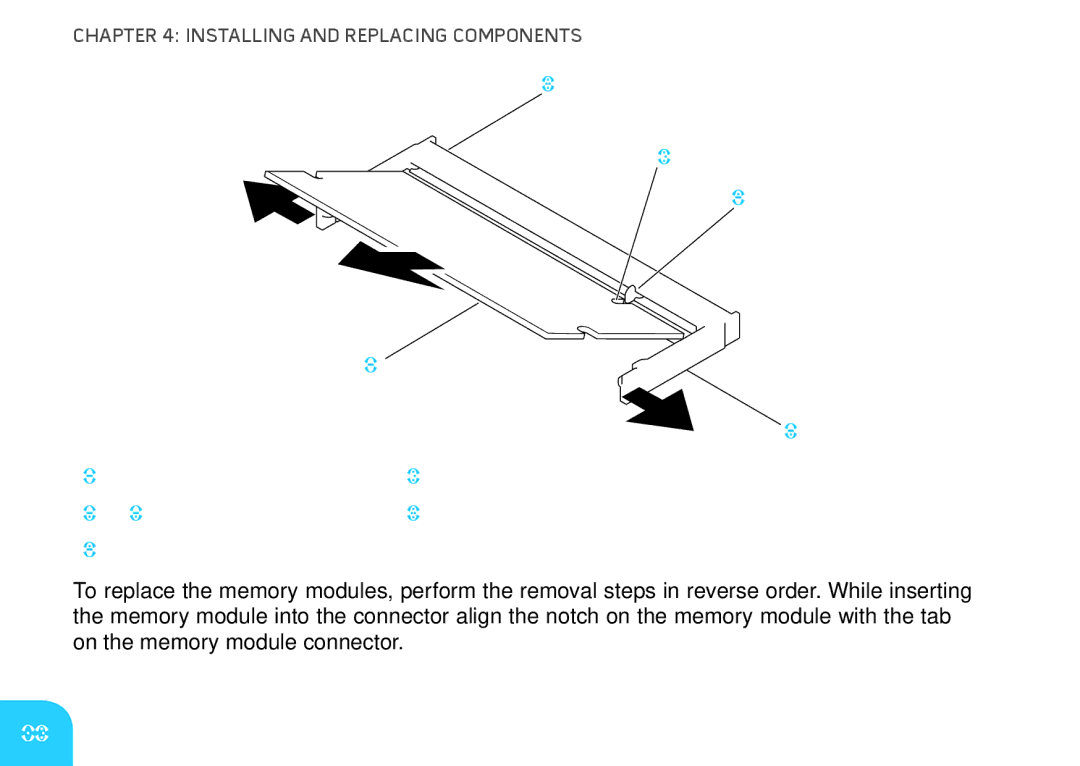
1 | memory module | 4 | notch |
2 | spring locks (2) | 5 | memory module connector |
3 | tab |
|
|
To replace the memory modules, perform the removal steps in reverse order. While inserting the memory module into the connector align the notch on the memory module with the tab on the memory module connector.
64