Removing and Installing Parts: Dell Dimension E520 Service Manual
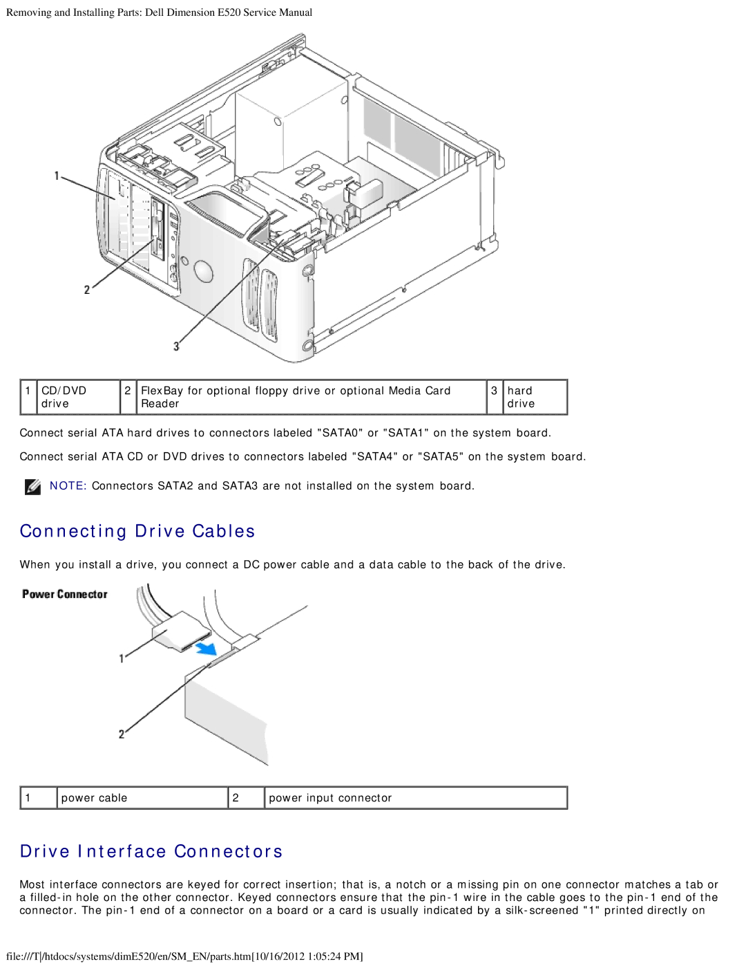
1 CD/DVD | 2 FlexBay for optional floppy drive or optional Media Card | 3 hard |
drive | Reader | drive |
Connect serial ATA hard drives to connectors labeled "SATA0" or "SATA1" on the system board.
Connect serial ATA CD or DVD drives to connectors labeled "SATA4" or "SATA5" on the system board.
NOTE: Connectors SATA2 and SATA3 are not installed on the system board.
Connecting Drive Cables
When you install a drive, you connect a DC power cable and a data cable to the back of the drive.
1 | power cable | 2 | power input connector |
Drive Interface Connectors
Most interface connectors are keyed for correct insertion; that is, a notch or a missing pin on one connector matches a tab or
a
file:///T/htdocs/systems/dimE520/en/SM_EN/parts.htm[10/16/2012 1:05:24 PM]