Attaching Guide Tube to Front Rail
1.Insert
2.Repeat for all other holes in front rail, making sure to fill the holes at both ends of the rail.
3.Remove right side guide tube end cap (I1) Fig. 16A.
Use a T25 screwdriver.
4.Slide guide tube hole (KK) Fig. 16B onto first hex head screw at the left side (as shown in Fig. 17). Make sure ruler tape (LL) Fig. 16B or Fig. 17 is to the front of the saw before you start. Work your way down and slide guide tube around all hex head screws (II) Fig. 15 until metal edge (MM) Fig. 18 on right end of guide tube (NOT THE PLASTIC CAP) is flush with right end (NN) of extension table. Use the included template (Z) to be sure straight edge of guide is flush with wood part of table, as shown in Fig. 18
5.Fully tighten all flange nuts (JJ) Fig. 15, attaching guide tube to the rail.
6. Replace right side guide tube end cap (I1) Fig. 16A.
I1 ![]()
Fig. 16A
LL
Fig. 17
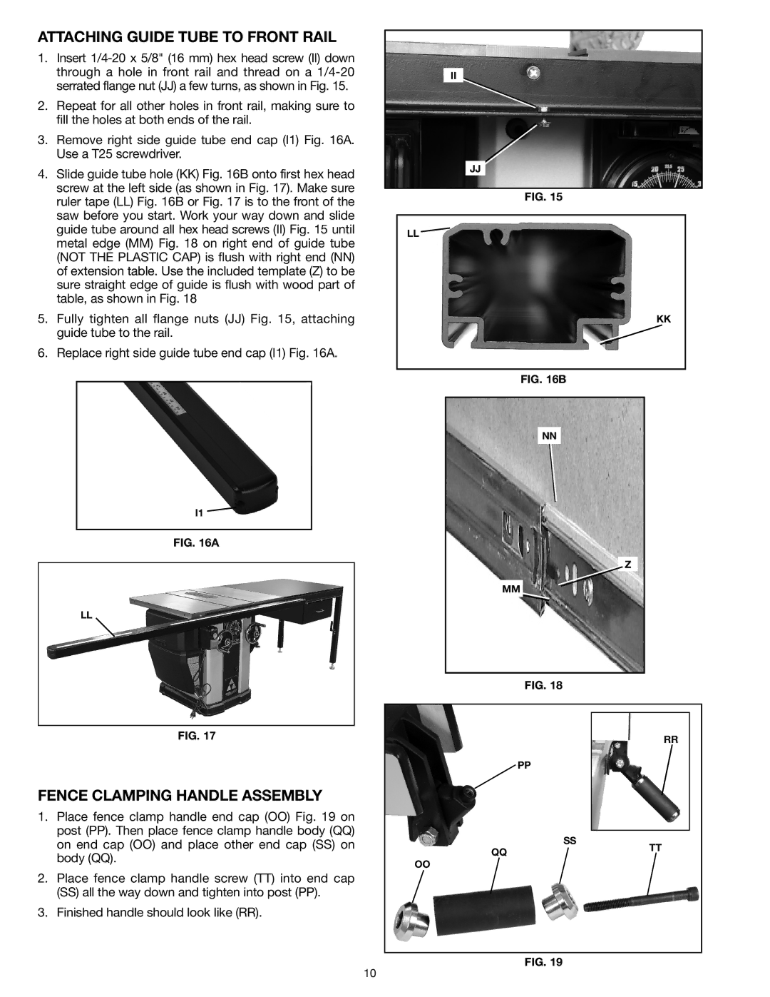
FENCE CLAMPING HANDLE ASSEMBLY
1.Place fence clamp handle end cap (OO) Fig. 19 on post (PP). Then place fence clamp handle body (QQ) on end cap (OO) and place other end cap (SS) on body (QQ).
2.Place fence clamp handle screw (TT) into end cap
(SS)all the way down and tighten into post (PP).
3.Finished handle should look like (RR).
II
JJ
Fig. 15
LL ![]()
KK
Fig. 16B
NN
Z
MM
Fig. 18
RR
PP
| SS |
|
| |
TT | ||||
|
| |||
|
|
|
OO
Fig. 19
10