CAMFOOT PLACEMENT
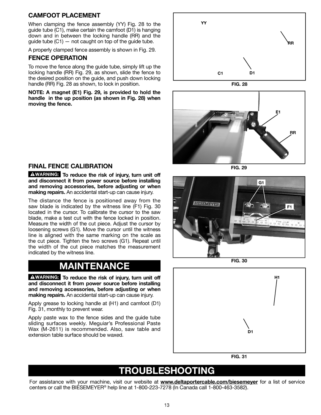
When clamping the fence assembly (YY) Fig. 28 to the guide tube (C1), make certain the camfoot (D1) is hanging down and in between the locking handle (RR) and the guide tube (C1) — not caught on top of the guide tube.
A properly clamped fence assembly is shown in Fig. 29.
FENCE OPERATION
To move the fence along the guide tube, simply lift up the locking handle (RR) Fig. 29, as shown, slide the fence to the desired position on the guide, and push down locking handle (RR) Fig. 28 as shown, to lock in position.
NOTE: A magnet (E1) Fig. 29, is provided to hold the handle in the up position (as shown in Fig. 28) when moving the fence.
FINAL FENCE CALIBRATION
![]() To reduce the risk of injury, turn unit off and disconnect it from power source before installing and removing accessories, before adjusting or when making repairs. An accidental
To reduce the risk of injury, turn unit off and disconnect it from power source before installing and removing accessories, before adjusting or when making repairs. An accidental
The distance the fence is positioned away from the saw blade is indicated by the witness line (F1) Fig. 30 located in the cursor. To calibrate the cursor to the saw blade, make a test cut with the fence locked in position. Measure the width of the cut piece. Adjust the cursor by loosening screws (G1). Move the cursor until the witness line is aligned with the same marking on the scale as the cut piece. Tighten the two screws (G1). Repeat until the width of the cut piece matches the measurement indicated by the witness line.
MAINTENANCE
![]() To reduce the risk of injury, turn unit off and disconnect it from power source before installing and removing accessories, before adjusting or when making repairs. An accidental
To reduce the risk of injury, turn unit off and disconnect it from power source before installing and removing accessories, before adjusting or when making repairs. An accidental
Apply grease to locking handle at (H1) and camfoot (D1) Fig. 31, monthly to prevent wear.
Apply paste wax to the fence sides and the guide tube sliding surfaces weekly. Meguiar’s Professional Paste Wax
YY
RR
C1D1
Fig. 28
E1
RR
Fig. 29
G1
F1
Fig. 30
H1
D1
Fig. 31
TROUBLESHOOTING
For assistance with your machine, visit our website at www.deltaportercable.com/biesemeyer for a list of service centers or call the Biesemeyer® help line at
13